Support structure of cooling air intake duct for intercooler of vehicle

a technology of cooling air intake duct and vehicle, which is applied in the direction of machines/engines, vehicle sub-unit features, and pedestrian/occupant safety arrangements, etc., can solve the problems of engine hood deformation, engine side wall deformation, and pedestrian head protection not being attained

Inactive Publication Date: 2009-04-28
MAZDA MOTOR CORP
View PDF13 Cites 37 Cited by
  • Summary
  • Abstract
  • Description
  • Claims
  • Application Information

AI Technical Summary

Benefits of technology

[0005]The present invention has been devised in view of the above-described problem, and an object of the present invention is to allow the engine hood to be properly deformed- without being prevented by the duct, thereby attaining the proper protection of the head of pedestrians.
[0007]When the pedestrian hits against the engine hood, the engine hood is deformed downward and thereby the duct located above the intercooler is deformed downward. Herein, according to the present invention, the front of the lower member is supported at the vehicle body and the rear of the upper member is supported at the vehicle body, while the rear lower face of the lower member has the seal member which is just pressed against the intercooler. Therefore, the impact load of the pedestrian hitting against the engine hood is transmitted to the duct so as to function to bend the duct supported at these front and rear support points. And, the upper member pushes the lower member, and thereby on the front attachment portion of the duct between the upper and lower members acts a compressing load which is constituted of a downward force from the upper member and an upward reaction force from the lower member. Meanwhile, on the rear attachment point of the duct acts a tension load which is constituted of an upward reaction force from the upper member and a downward force from the lower member. Thereby, the rear attachment portion of the duct is detached earlier than the front attachment portion of the duct by the crash load applied to the engine hood, so that the duct is split off, from the rear toward the front, into the upper member and the lower member. Accordingly, the engine hood is allowed to be properly deformed without being prevented by the duct, so that the protection of the head of pedestrians can be attained properly.
[0011]Accordingly, since the lower and upper members are supported on both end sides of a vehicle body in the longitudinal direction of the vehicle, the duct can be split to a large extent over the engine hood covering the intercooler at the pedestrian's hit. Thereby, the protection of the head of pedestrians can be attained surely.
[0013]Accordingly, since there exists a difference in the attachment strength between the front side and the rear side of the members, the detachment on the rear side can be promoted and thereby the split of the duct can be attained properly. Thus, the protection of the head of pedestrians can be attained more effectively.
[0015]When the duct is installed, the pins provided at the attachment portion of the resin-made upper member are inserted into the through holes formed at the lower member, and then melted and pressed to be collapsed. Thus, the enlarged portions are formed, and the upper and lower members are fixed by these enlarged portions. Also, the sealing function between the upper and lower members is improved by the flange provided at the lower member. Further, since the diameter size of the rear pins of the upper member is smaller than that of the front pins, the rear pins are broken earlier than the front pins by the crash load applied to the engine hood, so that the duct can be split off effectively from the rear pins. Thus, the protection of the head of pedestrians can be attained further surely.

Problems solved by technology

Therefore, since the distance between the intercooler and the engine hood becomes shorter, the conventional support structures of cooling air intake duct for intercooler of the vehicle have a problem that particularly a side wall of the box-shaped duct above the intercooler would not be deformed properly.
As a result, the engine hood would not be also deformed properly, and thereby the proper protection of the head of pedestrians would not be attained.

Method used


Image

  • Support structure of cooling air intake duct for intercooler of vehicle
  • Support structure of cooling air intake duct for intercooler of vehicle
  • Support structure of cooling air intake duct for intercooler of vehicle

Examples


Embodiment Construction

[0029]Hereinafter, embodiments of the present invention will be described referring to the accompanying drawings. Herein, the following discloses essentially preferred embodiments, which should not limit the present invention in a scope of its application or use.

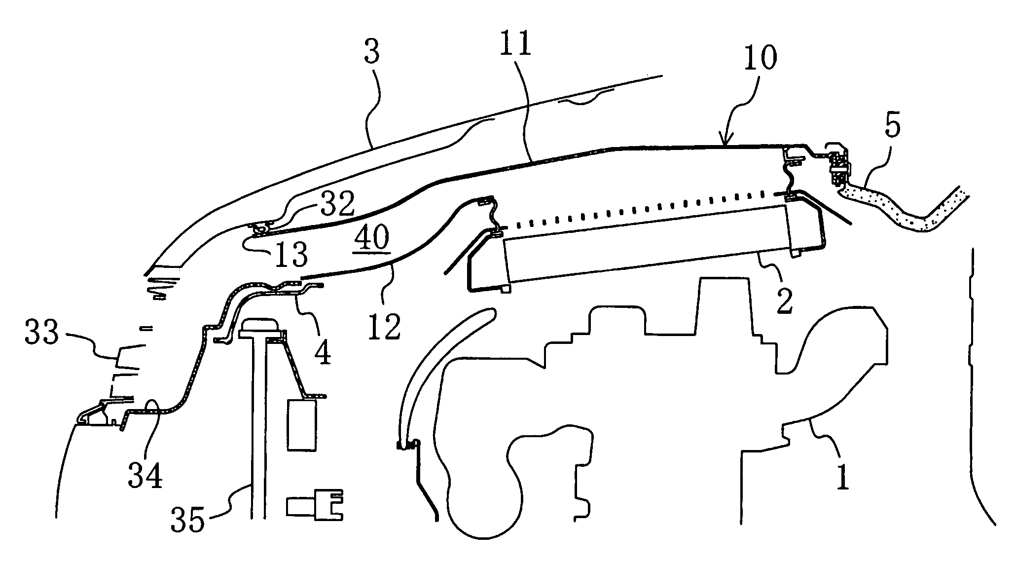
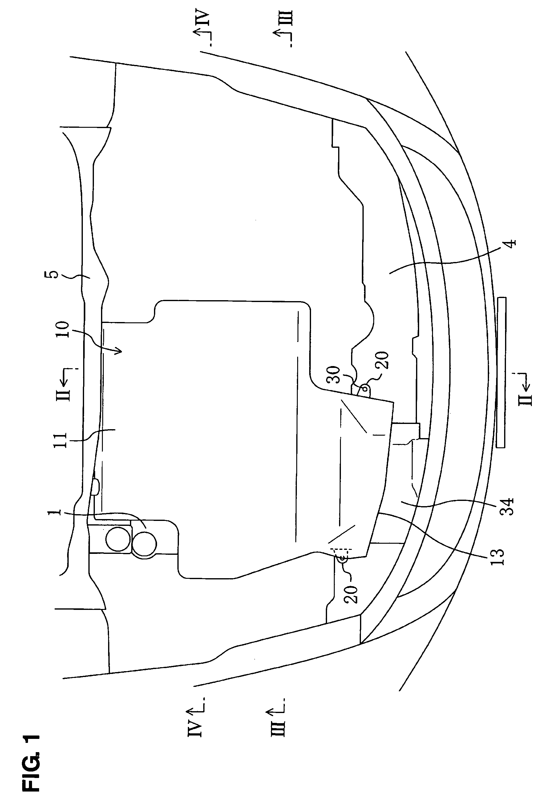
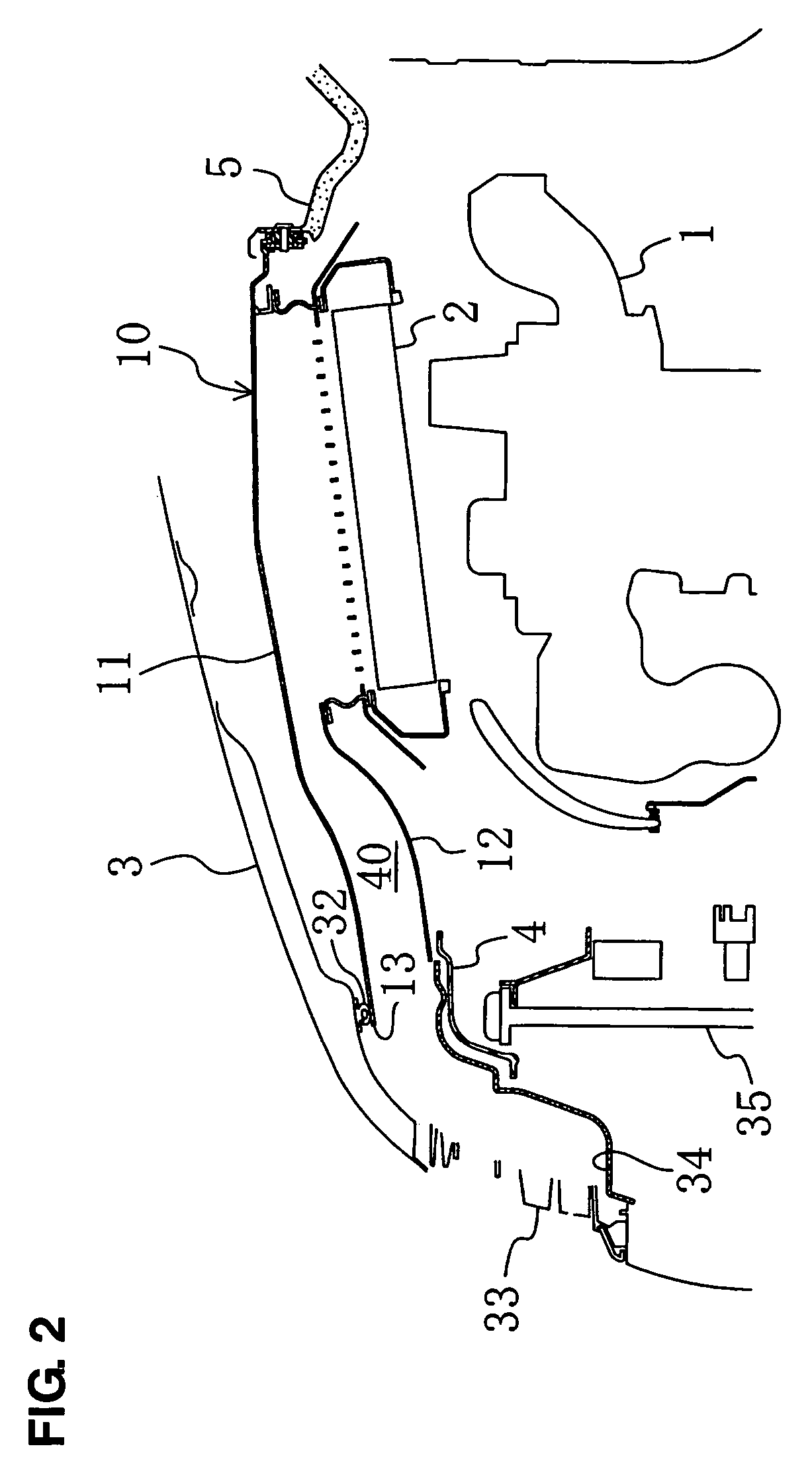
[0030]FIGS. 1 and 2 illustrate an engine room of a vehicle equipped with a support structure of cooling air intake duct for intercooler according to an embodiment of the present invention. In this engine room is provided an engine 1 equipped with a supercharger, which is disposed so as to extend in a lateral direction of the vehicle. An intercooler 2, which is made from metal, is disposed in a substantially flat position above the engine, specifically in such a manner that its rear is located slightly above its front. Herein, an engine hood 3 to cover the engine room is not illustrated in FIG. 1.

[0031]As illustrated in FIGS. 3 and 4, there is provided a duct 10, as a cooling air intake duct for intercooler, above an upper fa...


PUM


Abstract

The duct comprises the upper member and the lower member, which are formed separately and assembled integrally by being attached to one another. There is provided the seal member to interconnect the opening at the lower member and the intercooler, which is pressed against the upper face of the intercooler. The front side of the lower member is supported at the shroud panel, and the rear side of the upper panel is supported at the cowl panel. Thus, the rear attachment portion is detached earlier than the front attachment portion at the pedestrian's hit. Accordingly, the duct can be split surely and the engine hood can be allowed to be properly deformed without being prevented, so that the protection of the head of pedestrians can be attained properly.

Description

BACKGROUND OF THE INVENTION[0001]The present invention relates to a support structure of cooling air intake duct for intercooler of a vehicle with an engine equipped with a supercharger.[0002]Conventionally, vehicle designing for improving a roomy passenger compartment has been developed, and therefore there is a tendency of a relatively short engine room in a longitudinal direction of the vehicle. This tendency influences not only an engine installment but also layouts of an air cleaner, a battery and other components to some extent. Particularly, in the vehicle with the supercharged engine, it is necessary to provide a space for disposing an intercooler.[0003]Herein, the layout structure in which the intercooler of the vehicle is disposed in a flat position above the engine is known as disclosed in Japanese Patent Laid-Open Publication No. 2003-335173. In this structure, it will be necessary to provide a cooling air intake duct for intercooler which includes an air inlet at its fr...

Claims


Application Information

Patent Timeline
Patent Type & Authority Patents(United States)
IPC IPC(8): B60K11/00
CPCB60K11/08F01P11/10F02B29/0431B60R2021/343F01P2060/02Y02T10/146B60K13/02B60Y2306/01Y02T10/12
Inventor MURAMATSU, TAKAAKIKADOWAKI, TAKASHIFUJITA, NORIAKI
Owner MAZDA MOTOR CORP
Why Eureka
Try Eureka