Networking cable with lighting system for cable tracing

a network cable and lighting system technology, applied in the field of cables, can solve the problems of difficult identification of time-consuming and labor-intensive cable tracing methods, and difficulty in identifying which cable connectors belong to which waveguides, and achieve the effect of reducing the length of the cabl

Inactive Publication Date: 2009-04-28
NORTH TODD MICHAEL
View PDF38 Cites 32 Cited by
  • Summary
  • Abstract
  • Description
  • Claims
  • Application Information

AI Technical Summary

Benefits of technology

[0007]The present invention employs a cable which includes cable connectors at opposed ends of a waveguide, wherein the waveguide carries a lighting system. In one embodiment, the lighting system includes three or more light emitters, wherein the light emitters are connected together with conductive lines. A potential difference between the conductive lines activates the light emitters so the cable can be traced. The light emitters are spaced apart from each other along the length of the waveguide so the cable length can be reduced while still retaining the cable tracing benefits provided by them. In another embodiment, the lighting system includes a support structure which carries a plurality of light emitters. The support structure is repeatably removable from the waveguide so that an existing waveguide can be modified by attaching the support structure to it.

Problems solved by technology

The networking cables often extend in such a way that it is difficult to identify which cable connectors belong to which waveguide.
However, a person generally uses trial and error by connecting the sound sensor to the different cable connectors at the opposed end of the bundle until the sound signal is detected.
This method of cable tracing is tedious and time consuming, and sometimes the electrical test signal is not strong enough to cause the sound sensor to emit sound.
However, the light emitters are positioned at the cable connectors, which makes it difficult to identify the corresponding waveguide in between.
Further, since the light emitters are positioned at the cable connectors, it is also difficult to reduce the length of the waveguide without removing a light emitter.
Removing a light emitter in the cables disclosed by Dannenmann reduces the ability to trace the cable.

Method used


Image

  • Networking cable with lighting system for cable tracing
  • Networking cable with lighting system for cable tracing
  • Networking cable with lighting system for cable tracing

Examples


Embodiment Construction

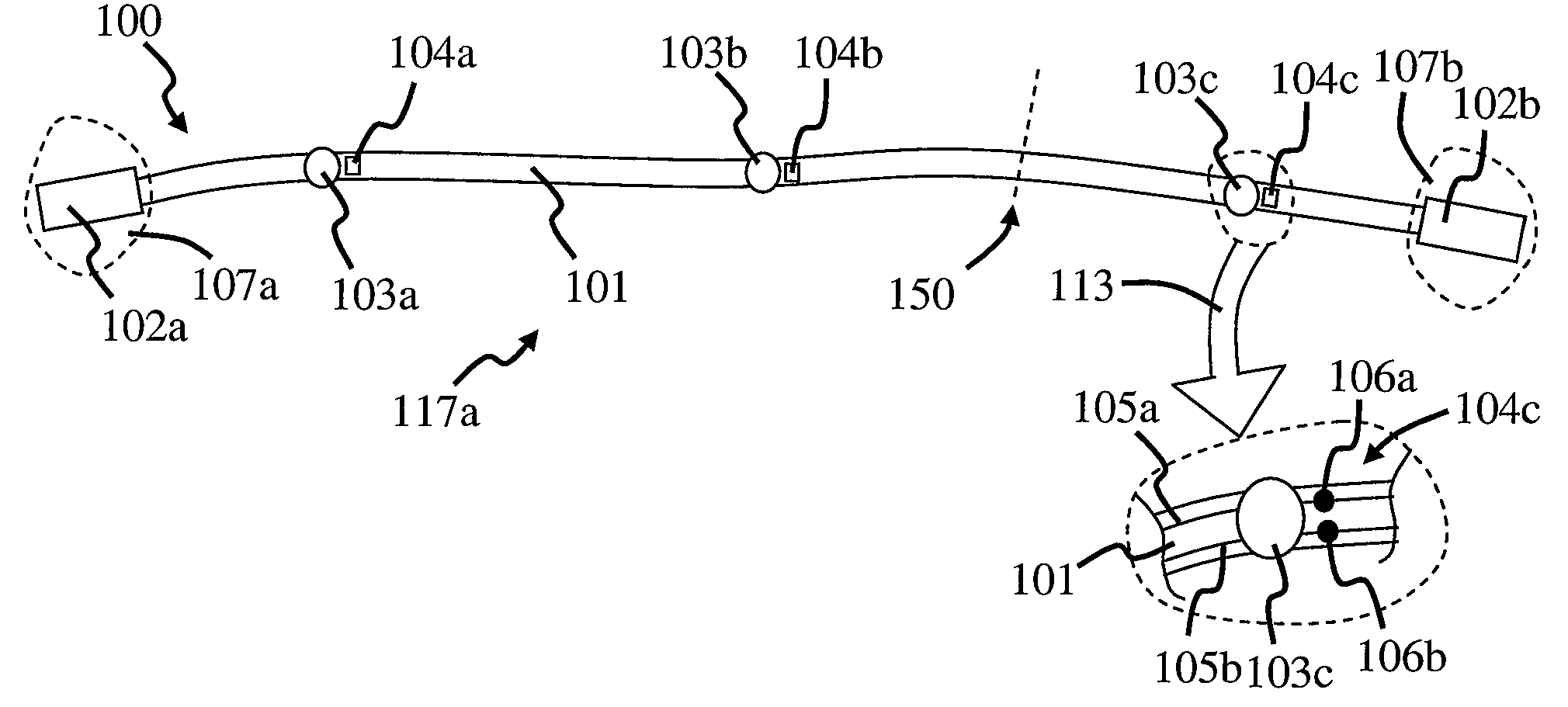
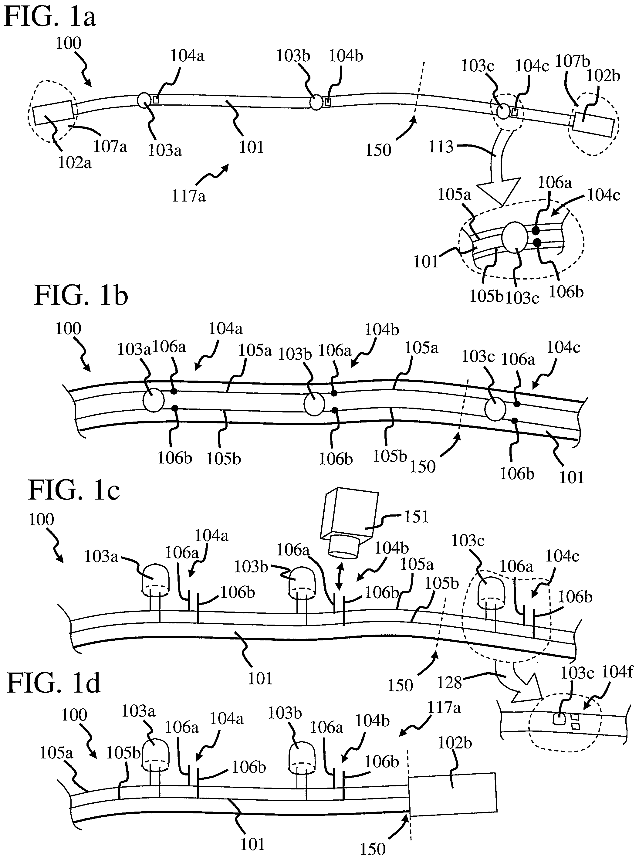
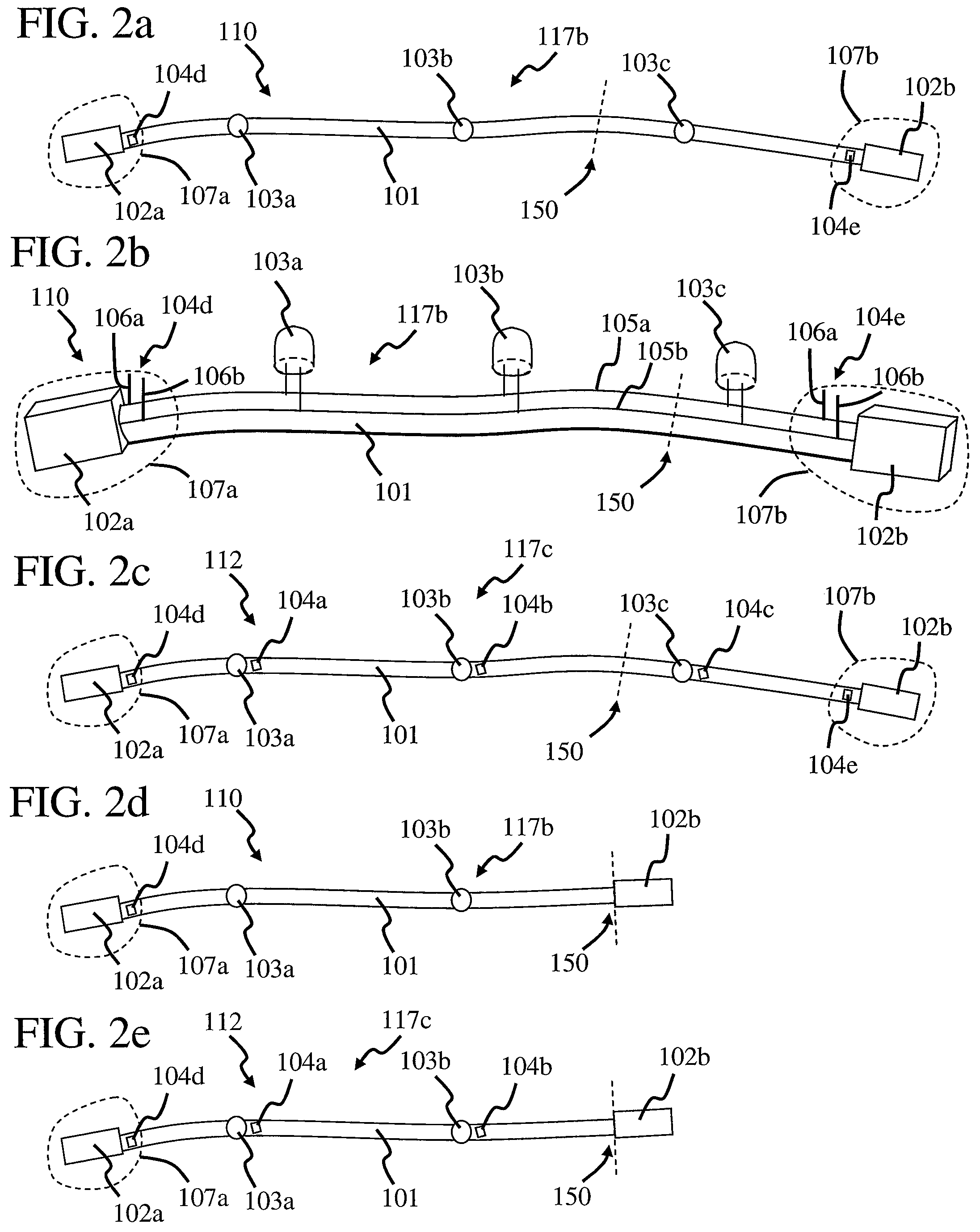
[0033]FIGS. 1a and 1b are top and perspective views, respectively, of a networking cable 100, in accordance with the invention. In this embodiment, networking cable 100 includes a waveguide 101 with cable connectors 102a and 102b at opposed ends. It should be noted that, in networking cables, cable connectors 102a and 102b are generally of the same type. For example, they are generally both male or both female, although one can be male and the other can be female in some embodiments.

[0034]The waveguide of a networking cable generally has characteristic impedance between about 50 ohms to 100 ohms, and allows the flow of one or more data signals therethrough. The data signals can be combined together and separated from each other. The data signals generally correspond to digital data which flows through the waveguide at data rates that are typically greater then one to two million bits per second (Mbps). For example, a typical computer network flows data at ten Mbps, although there ar...


PUM


Abstract

A cable includes a waveguide with a lighting system removeably attached to it. The lighting system includes a plurality of light emitters extending along the waveguide and connected together with conductive lines. The lighting system also includes light emitter connectors which can be engaged with a power source to activate the light emitters. The activation of the light emitters is useful in cable tracing because it indicates where the waveguide extends.

Description

BACKGROUND OF THE INVENTION[0001]1. Field of the Invention[0002]This invention relates generally to cables for transferring data.[0003]2. Description of the Related Art[0004]Most computer networks include computers in communication with each other through networking cables. The cables can be of many different types, such as coaxial and Ethernet cables, and generally include a waveguide with cable connectors at opposed ends. In a typical setup, a large number of networking cables are grouped together in a bundle and extend for long distances through a building so that the opposing cable connectors are away from each other. The networking cables often extend in such a way that it is difficult to identify which cable connectors belong to which waveguide. The identifying of cable connectors is often referred to as cable tracing.[0005]There are several methods used in cable tracing. One method involves flowing an electrical test signal with a toner through a cable connector at one end of...

Claims


Application Information

Patent Timeline
Patent Type & Authority Patents(United States)
IPC IPC(8): F21S4/00
CPCG02B6/001G02B6/447G02B6/4469G02B6/562
Inventor NORTH, TODD MICHAEL
Owner NORTH TODD MICHAEL
Why Eureka
Try Eureka