Method and apparatus for permanent and safe disposal of radioactive waste

a radioactive waste and permanent disposal technology, applied in nuclear engineering, radioactive decontamination, nuclear engineering, etc., can solve the problems of not being considered useful disposal locations, unable to meet the needs and the capacity of the earth's core is so vast as to be limitless for all practical purposes

Inactive Publication Date: 2009-04-28
GENERAL ELECTRIC CO
View PDF1 Cites 2 Cited by
  • Summary
  • Abstract
  • Description
  • Claims
  • Application Information

AI Technical Summary

Benefits of technology

[0012]These subduction faults provide a natural pathway for nuclear waste disposal with an increase in safety and security, at a fraction of the cost over the long term, as compared to the storage methods now being used and considered.
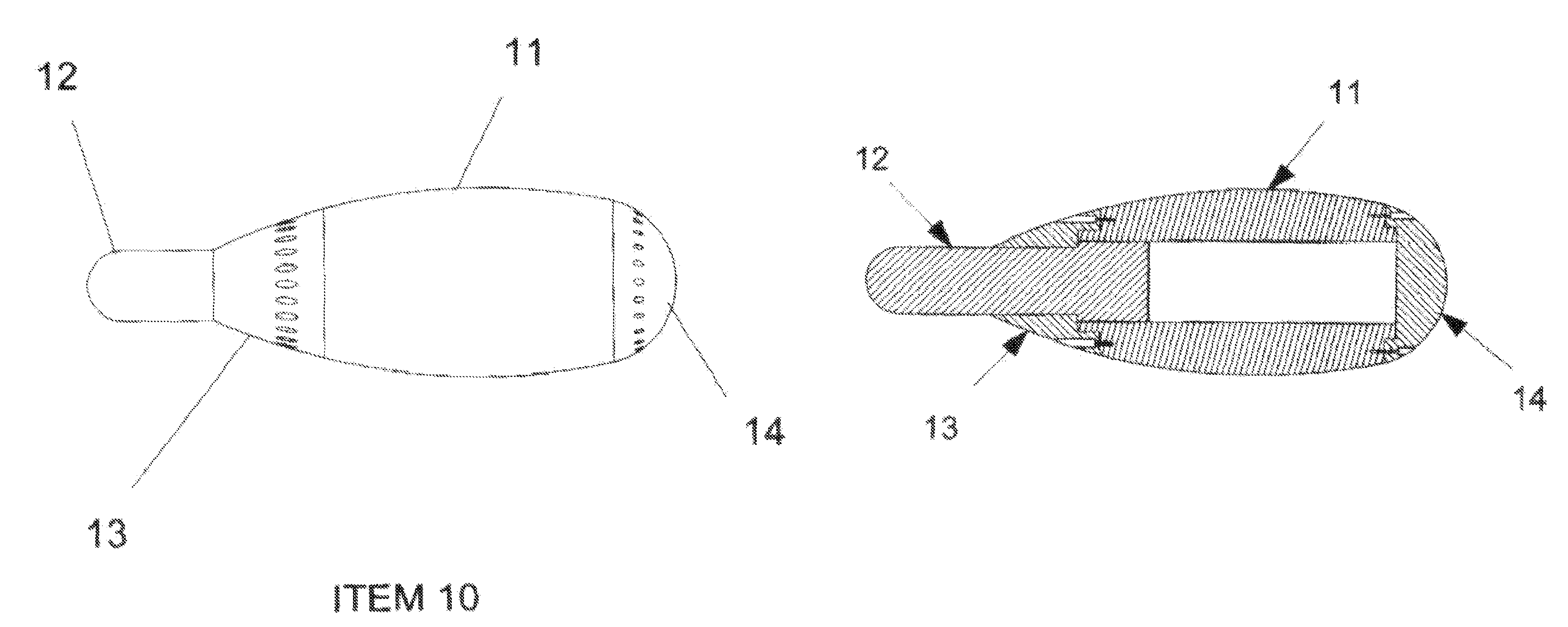
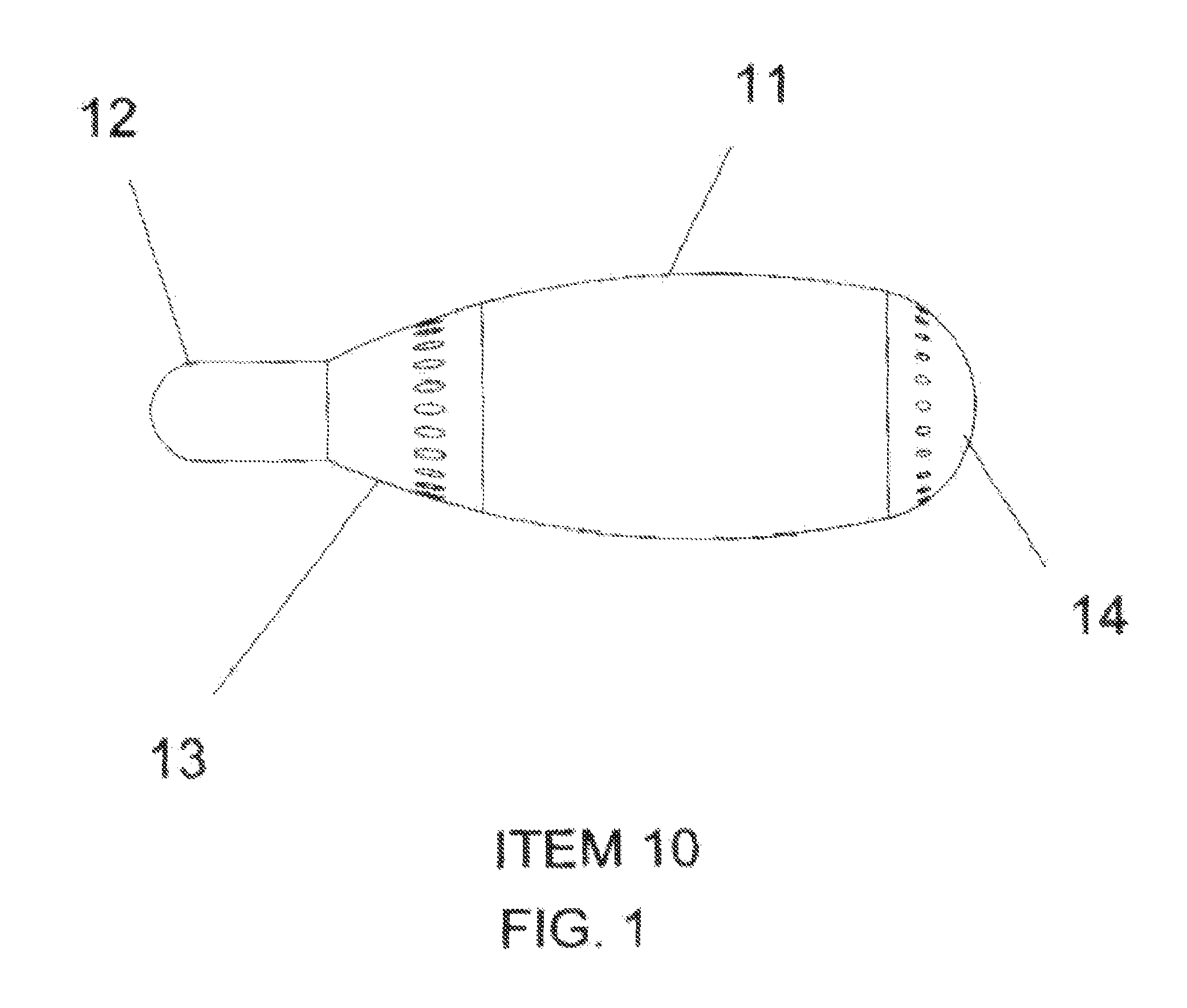
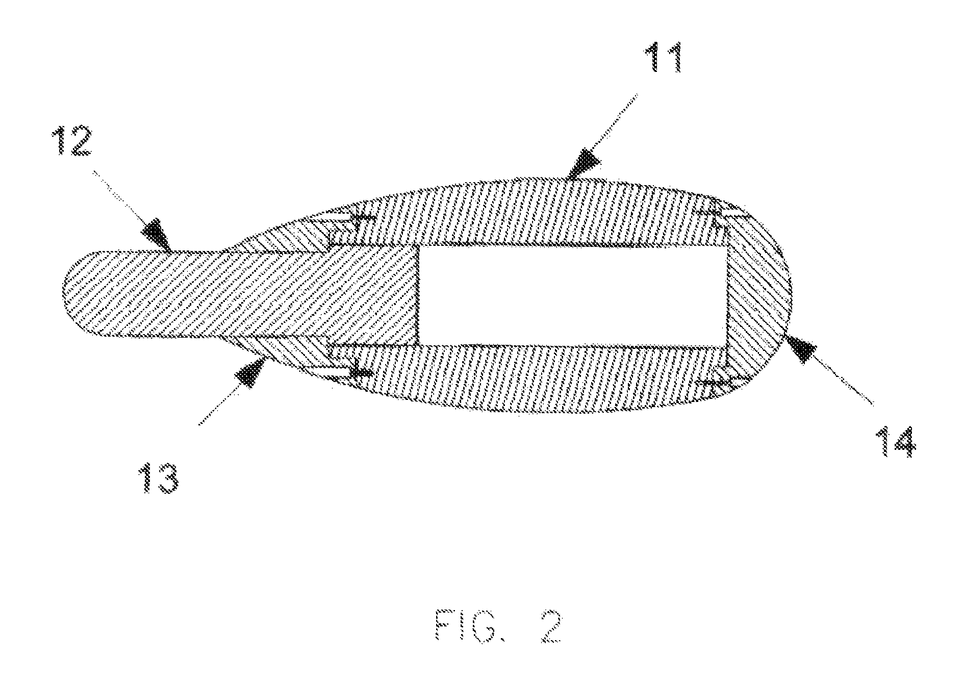
[0014]To eliminate the possibility of leakage, the container must be of a pressure-equalizing design. These disposal containers are designed to be filled with high- or low-level radioactive waste, transported to the ocean floor next to a subduction zone, and buried in the mud. A key feature of the hardware is the ability to compensate for extreme increases in pressure without damage to the container. This is accomplished by creating a container that is essentially a piston within a cylinder, whereas the piston is free to move into the cylinder as far as necessary to equalize the pressures within and without. Some resistance to the equalization of pressures will occur as the spent fuel rods resist compression, but cuts made in the fuel rod bundles will cause their collapse within a certain delta of pressure. This has the advantage of insuring that any leak travels from outside to inside the container—therefore no contaimination external to the container will occur in the event of damage to the container or manufacturing flaw.

Problems solved by technology

The other two subduction zones-one in the Near East and the other on the China-India border-are not considered useful disposal locations, as they are not on an ocean floor and will not provide the same level of security as those subduction zones which are on an ocean floor.
The capacity of the earth's core is so vast as to be limitless for all practical purposes.

Method used


Image

  • Method and apparatus for permanent and safe disposal of radioactive waste
  • Method and apparatus for permanent and safe disposal of radioactive waste
  • Method and apparatus for permanent and safe disposal of radioactive waste

Examples


Embodiment Construction

[0024]The invention will now be described in detail with reference to the attached drawing figures. It should be understood that the drawings are meant to be merely illustrative and are not necessarily drawn to scale.

[0025]Referring now to FIG. 1, the present invention is designed to provide the nuclear power industry and other organizations that generate nuclear waste, including both low- and high-level waste, with a special container 10 for nuclear waste disposal. This container resists increasing temperatures by being made of stainless steel or other suitable material. Stainless steel starts to soften at 1100° C. and melts at 1400°-1500° C. Other materials may be used provided that the melting point is greater than that of stainless steel. Ceramic materials, for example, are a usable alternative to stainless steel. The container 10 includes a chamber body 11 having a cylindrical inner chamber; a piston plug 12 which slides within the cylindrical inner chamber, thereby compensatin...


PUM


Abstract

A method of disposing of radioactive waste comprising the steps of: providing a pressure-equalizing container; filling the pressure-equalizing container with radioactive waste; and burying the waste filled container in a subduction fault region of the earth's crust. For a preferred embodiment of the process, the waste filled containers are buried in the mud on the ocean floor in a subduction fault region. Preferably, the containers are placed on the ocean side of the fault, rather than the continental shelf side. The pressure-equalizing container is preferably fabricated from stainless steel, with a lead seal, although containers fabricated from ceramic materials may also be used. The waste-filled containers are transported by ship to the area above a subduction fault, and an unpressurized, remote-controlled “submarine crawler” takes a number of containers to the ocean floor and buries them there, individually, in the mud or sediments.

Description

[0001]This application is a continuation-in-part of application Ser. No. 10 / 365,205 which was filed on Feb. 11, 2003 now abandoned and titled Method and Apparatus for Permanent and Safe Disposal of Radioactive Waste, and which has a priority date based on Provisional Patent Application No. 60 / 355,620, which has a filing date of Feb. 11, 2002.BACKGROUND OF THE INVENTION[0002]1. Field of the Invention[0003]This invention relates to the apparatus for permanently disposing of high and low-level nuclear waste in subduction faults in oceans.[0004]2. Description of the Prior Art[0005]One of the primary problems associated with the generation of electrical power via nuclear fusion is the disposal of radioactive waste. Uranium-fueled, light-water reactors, which are commonly used in the U.S., produce plutonium 239 as one of the waste byproducts. Not only is plutonium 239 extremely poisonous, it has a half-life of 24,400 years. That means that this element would be dangerous to man for about ...

Claims


Application Information

Patent Timeline
Patent Type & Authority Patents(United States)
IPC IPC(8): G21F5/00G21F9/00G21F9/24G21F9/34
CPCG21F9/24G21F9/34G21Y2002/50G21Y2002/60G21Y2004/601G21F5/005
Inventor ENGELHARDT, DEAN STEWART
Owner GENERAL ELECTRIC CO
Why Eureka
Try Eureka