Method for manufacturing lighting device, image display, liquid crystal monitor, liquid crystal television, liquid crystal information terminal, and light guide plate

a technology of liquid crystal monitors and lighting devices, which is applied in the direction of optics, instruments, optical light guides, etc., can solve the problems of low light utilization efficiency, no reflection tapes can be provided, and the density of scattering dots b>1004/b> has an upper limit by safety considerations, so as to improve the apparent brightness and increase the luminance

Inactive Publication Date: 2009-04-28
JAPAN DISPLAY CENTRAL CO LTD
View PDF24 Cites 33 Cited by
  • Summary
  • Abstract
  • Description
  • Claims
  • Application Information

AI Technical Summary

Benefits of technology

[0119]In addition, the above-mentioned luminance distribution alteration means may determine a panoramic luminance distribution of the above-mentioned video signal on a screen and alter the above-mentioned luminance distribution on the light exit surface according to said determined panoramic luminance distribution.
[0120]This configuration can improve an apparent brightness by determining a peak of the luminance from, for example, the above-mentioned panoramic luminance distribution and increasing the luminance at or around t he peak on the display screen.

Problems solved by technology

This results in a low light utilization efficiency.
In this case, no reflection tape can be provided.
However, the density of the scattering dots 1004 has an upper limit by safety considerations in manufacturing.
The degree of coalescence varies each time of printing, which interferes stable fabrication.
However, the approach of incorporating the diffusing material into the light guiding plate to scatter the beams of light can only improve the scattering efficiency within the light guiding plate.
It is difficult to control, at the same time, the luminance distribution on the light exit surface of the light guiding plate.
Random variations cannot be achieved for settings of the luminance distribution of the backlight.
Thus, no liquid crystal display with a conventional backlight can change the settings of the luminance distribution according to the utility of it.
This may cause a problem of irregularities in black display.
Consequently, deterioration of light condensing characteristic caused by deformation of the prism sheet 1033 due to heat would be a problem.

Method used


Image

  • Method for manufacturing lighting device, image display, liquid crystal monitor, liquid crystal television, liquid crystal information terminal, and light guide plate
  • Method for manufacturing lighting device, image display, liquid crystal monitor, liquid crystal television, liquid crystal information terminal, and light guide plate
  • Method for manufacturing lighting device, image display, liquid crystal monitor, liquid crystal television, liquid crystal information terminal, and light guide plate

Examples


embodiment 1

[0199]The Embodiment 1 of the present invention shows a configuration example of a lighting device of which luminance distribution may be determined arbitrarily.

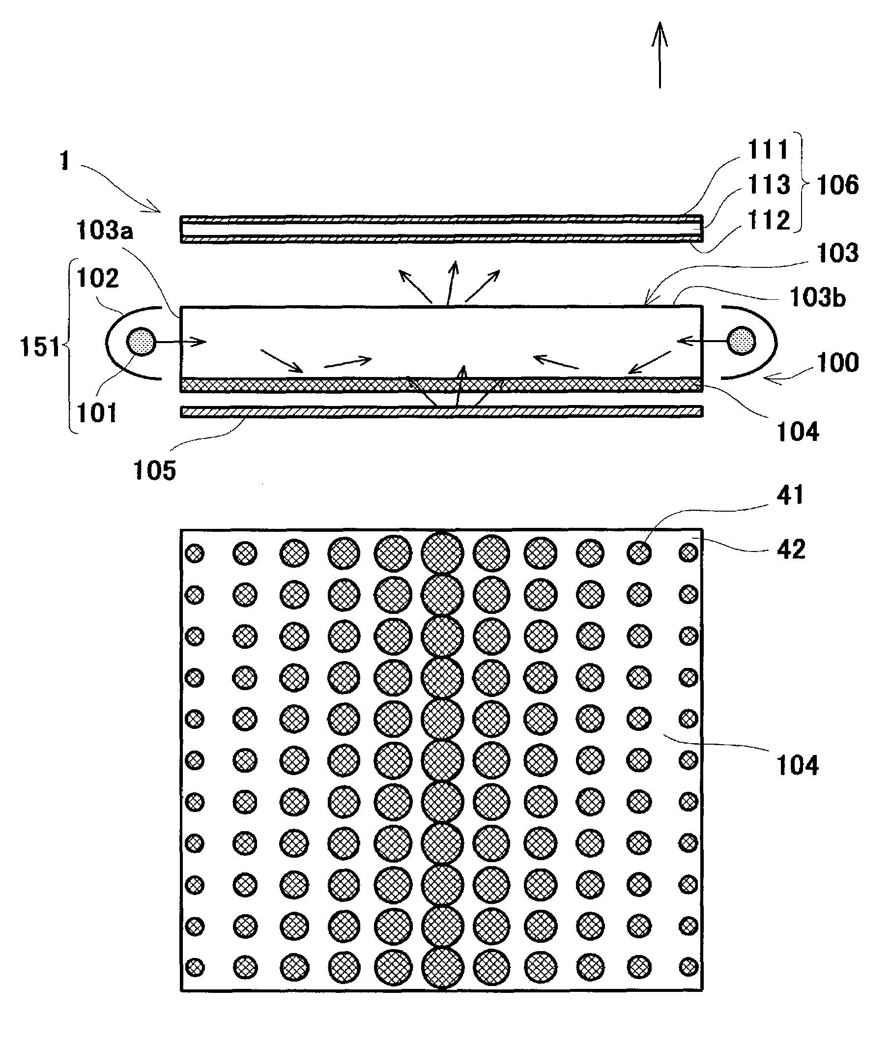
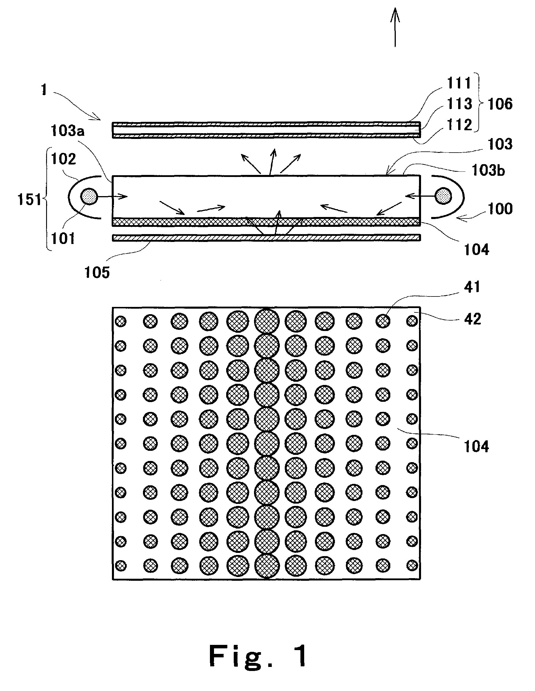
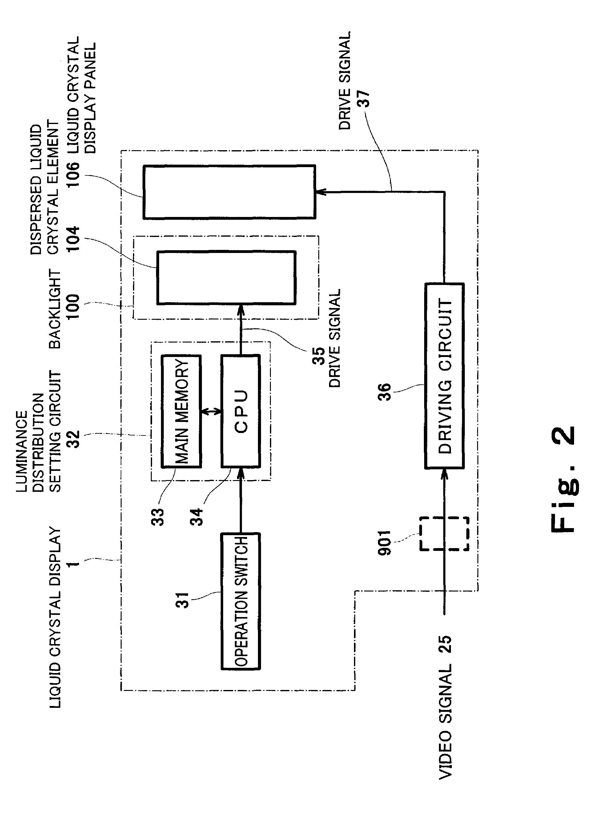
[0200]FIG. 1 is a view that schematically illustrates configurations of a lighting device and of an image display in which the device is used, according to this embodiment. In the figure, (a) is a cross-sectional view, and (b) is a plan view showing a dot pattern of a dispersed liquid crystal element shown in (a). FIG. 2 is a block diagram showing a configuration of a control system used in the image display shown in FIG. 1(a). In FIG. 1(a), the upper direction of an image display is considered as an X-direction, as a matter of convenience.

[0201]In FIG. 1(a), this embodiment illustrates a liquid crystal display as an image display, and a backlight 100 for liquid crystal displays as a lighting device.

[0202]The backlight 100 is placed beneath a liquid crystal panel (hereinafter, referred to as a “liquid crystal display element...

example 1

[0209]In FIGS. 1(a) and (b), the dot pattern was generated on the dispersed liquid crystal element 104 as follows. More specifically, the dots 41 were arranged into an array. Where y represents the diameter of a dot 41, said diameter y was made to vary according to the linear function of “y=a×r” (a: proportional coefficient), said function being in proportion to the distance r from the light emitters 101 disposed on the right and left sides of the light guiding plate 103. The proportional coefficient a was determined in such a manner that the central dot 41 which was the largest diameter had a diameter of approximately 2 mm, and the pitch between the dots 41 was set to be approximately 1.5 to 3 mm.

[0210]The light guiding plate 103 used was rectangular in shape with a diagonal of 7 inches (hereinafter, what the diagonal is x inch(es) is referred to as an “x-inch size”) and a thickness of approximately 10 mm. A cold cathode tube that is designed to provide approximately 100 W output w...

example 2

[0212]In this example, the diameter of a dot 41 was made to vary in proportion to the square of the distance r from the light emitters 101 disposed on the right and left sides of the light guiding plate 103, according to the linear function of “y=a ×r ×r”. Other factors are similar to those in the Example 1. Then, the luminance distribution was measured on the upper surface of the light guiding plate 103. The luminance at the center thereof was about 6000 candelas. The luminance at a position 0.9 inches away from the edge along the diagonal line was about 3000 candelas. The luminance around the periphery was about 50% of the luminance at the center. Thus, the luminance distribution with a large difference in luminance between the periphery and the center was obtained.

[0213]The Examples 1 and 2 revealed that the luminance distribution may be varied arbitrarily by forming a certain scattering pattern using electric fields applied to the dispersed liquid crystal element 104. The dot pa...


PUM


Abstract

The present invention is directed to provide, for example, a lighting device and an image display, with which higher luminance and others can be achieved. In order to achieve this object, an image display of the present invention is formed in a lighting device (100) including a light source (102), a light guiding plate (103) that is disposed in such a manner that the light from the light source (102) is allowed to enter it through an end face (103a) thereof, and a reflecting surface (105) that is opposed to one major surface (103c) of the light guiding plate (103), wherein the one major surface (103c) of the light guiding plate (103) has a constant scattering layer (121) formed thereon which is adapted to transmit the incident light to scatter it at a predetermined rate, and the constant scattering layer (121) has a distribution and scattering structure (114) formed there on which is adapted to transmit the incident light to scatter it at a percentage that varies according to the distance from the above-mentioned light source (102).

Description

TECHNICAL FIELD[0001]The present invention relates to a method for manufacturing a lighting device, an image display, a liquid crystal monitor, a liquid crystal television, a liquid crystal information terminal, and a light guiding plate.BACKGROUND ART[0002]Liquid crystal displays, as an example of conventional image displays, comprise a liquid crystal display panel, a backlight that is disposed beneath the liquid crystal display panel to supply light to the liquid crystal display panel, and a circuit board used to drive the liquid crystal display panel. The liquid crystal display panel has two transparent glass substrates on which electrodes made of a transparent conductive thin film, an alignment layer, and others are laminated. The transparent glass substrates are assembled at a predetermined distance with their lamination surfaces opposing to each other. Liquid crystal is filled and sealed between these glass substrates. A polarizer is provided outside the glass substrates.[0003...

Claims


Application Information

Patent Timeline
Patent Type & Authority Patents(United States)
IPC IPC(8): G09G3/36F21V8/00
CPCG02B6/0036G02B6/0041G02B6/0046G02B6/0053G02B6/0055G02B6/0061
Inventor OGIWARA, AKIFUMIKOMORI, KAZUNORIASAYAMA, JUNKOKURATOMI, YASUNORI
Owner JAPAN DISPLAY CENTRAL CO LTD
Why Eureka
Try Eureka