LED luminance-augmentation via specular retroreflection, including collimators that escape the étendue limit

a technology of specular retroreflection and luminance augmentation, which is applied in the field of beamforming illumination systems, can solve the problems of étendue-invariance limitation of their performance, and achieve the effects of increasing the effective luminance of sources, and reducing the diameter of optical systems

Active Publication Date: 2011-01-25
LIGHT ENGINE
View PDF19 Cites 2 Cited by
  • Summary
  • Abstract
  • Description
  • Claims
  • Application Information

AI Technical Summary

Benefits of technology

[0011]Beyond the efficiency of retroreflection, various optical errors will cause some of this light to miss the LED, generating an intercept efficiency ρI, typically of up to about 90%. In some of the preferred embodiments disclosed herein, this value is nearly 100%. An LED's diffuse reflectivity, ρL=85% for a white LED, overlays this return light on the LED's original emission, enhancing the apparent brightness of the LED.
[0014]In a more favorable case, ρr=98% and ρI=98%, we have FR=61% for an aperture that is 25% the original area (50% of the original diameter), giving Fe=54%, and for a 50% area aperture, FR=41% and Fe=71%. These improved efficiencies could justify the extra expense of the superior retroreflective efficiency.
[0016]Many of the present luminaires can be categorized into two main types of collimator apparatus. The first type of collimator increases the source's effective luminance (and the étendue of the exit aperture of the device) but the overall size of the optic or diameter of the optical system, including the retroreflecting features, is approximately the same as a standard collimator with the same source. The second type of collimator increases the effective luminance of the source but also decreases the diameter of the optical system compared to the “standard” optic. In this case the diameter of the new optic will be smaller than the standard optic that achieves the same degree of collimation with the same source. Both these apparatus escape the classical étendue constraints, but the second type has the advantage over the first that the diameter of the overall system (not just the optical exit aperture) is reduced. Therefore the second type of apparatus should be useful for such applications as automotive forward or rear lighting, where frontal real estate on the vehicle is scarce but luminous performance cannot be compromised. Virtually all of the embodiments disclosed herein are of the second type, but the principles taught also can be applied to those of the first type.

Problems solved by technology

The primary limitation upon their performance is étendue-invariance, by which the angular radius θ of the beam is determined by the ratio of source diameter d to aperture diameter D: sin θ=d / D, when the source radiates into a hemisphere.

Method used


Image

  • LED luminance-augmentation via specular retroreflection, including collimators that escape the étendue limit
  • LED luminance-augmentation via specular retroreflection, including collimators that escape the étendue limit
  • LED luminance-augmentation via specular retroreflection, including collimators that escape the étendue limit

Examples


Embodiment Construction

[0058]A better understanding of various features and advantages of the present luminaires will be obtained by reference to the following detailed description of the invention and accompanying drawings, which set forth illustrative embodiments. Corresponding reference characters indicate corresponding components throughout the several views of the drawings.

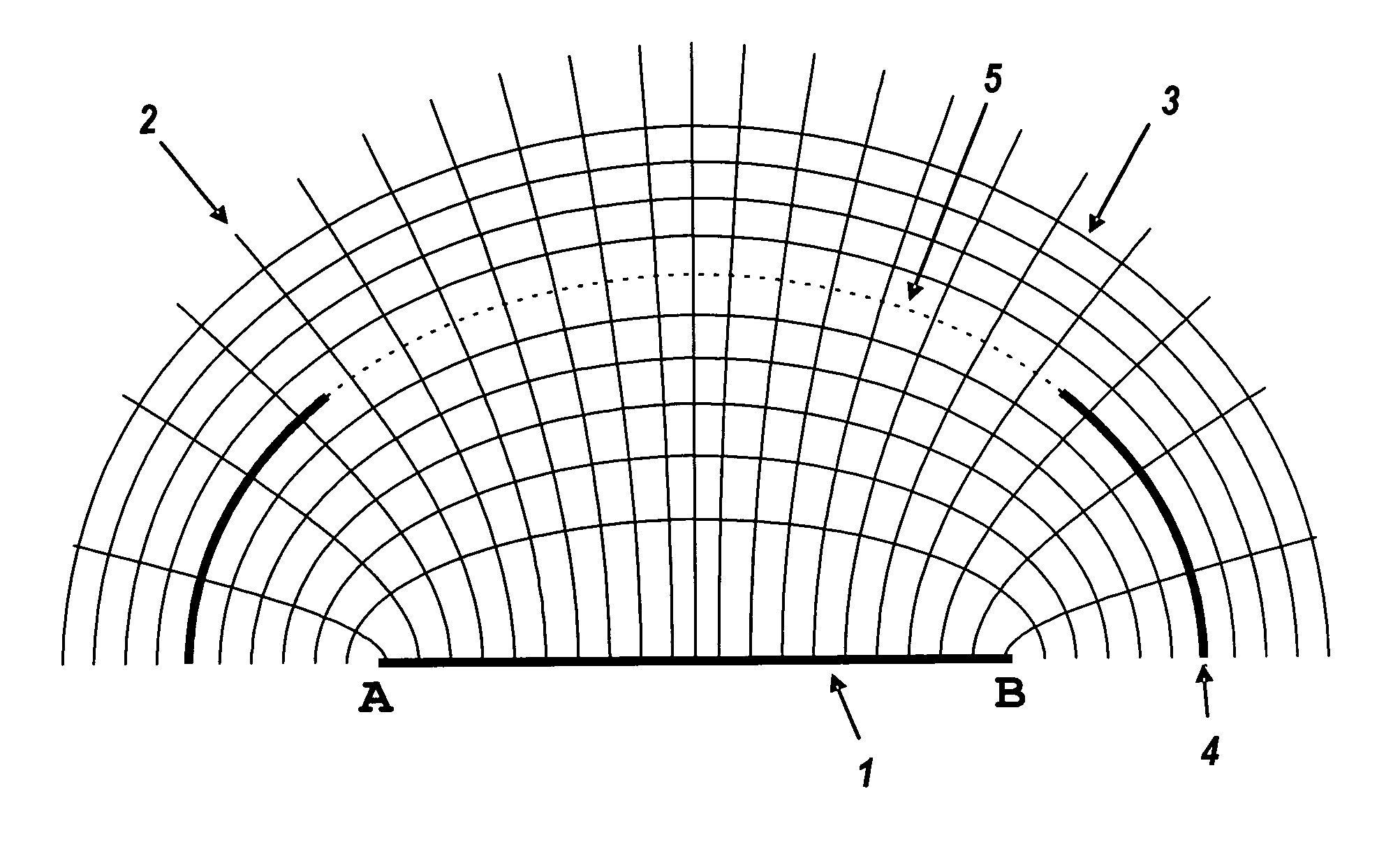
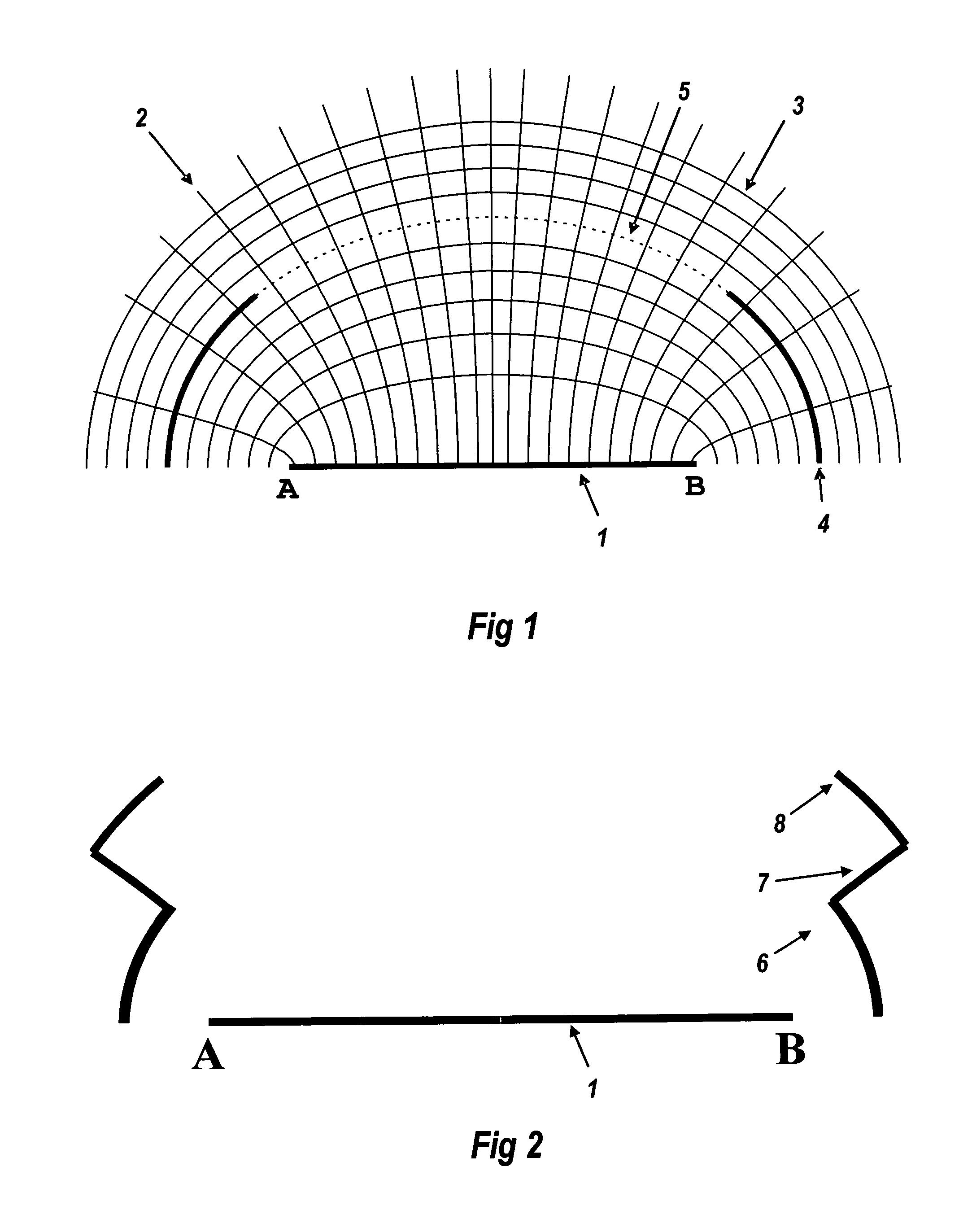
[0059]Flowlines are well known in the field of non-imaging optics, being defined at any point receiving light from a source. At some viewing point, rays are received from across the source, and the rays from the source's edges define the edge of the source image. In the case of the following Figures, the flowlines are everywhere tangent to the bisectors of the angle formed by the rays from the two edges of the source.

[0060]FIG. 1 is a two-dimensional view across a light source 1, emitting upwards between point A and point B. Flowlines 2 are confocal hyperbolas with those points A and B as their foci. At every point upon the flowlin...


PUM


Abstract

The diffuse reflectivity of an LED source is utilized to recycle some of its emission, thereby enabling a luminaire to escape the étendue limit. Retroreflectors intercept the rays destined for the outer part of the luminaire aperture, which can then be truncated. The resulting smaller aperture has the same beam-width as the full original, albeit with lesser flux due to recycling losses. A reduction to half the original area is possible.

Description

BACKGROUND OF THE INVENTION[0001]The present invention relates generally to beam-forming illumination systems, and more specifically to those with sufficiently narrow solid angles for the output beam to be called collimators. Examples are flashlights and searchlights. The primary limitation upon their performance is étendue-invariance, by which the angular radius θ of the beam is determined by the ratio of source diameter d to aperture diameter D: sin θ=d / D, when the source radiates into a hemisphere. The beamwidth is twice the angular radius and usually is defined as full width at half maximum (FWHM).[0002]Light emitting diodes (LEDs) are an example of such a hemispheric source. Their small size and ever-improving luminous efficacy are propelling them into market predominance in many fields of lighting. Since their hemispheric emission is too wide for most lighting tasks, LEDs are installed in luminaires that generate narrower output angles. So far, LED flashlights are gaining mark...

Claims


Application Information

Patent Timeline
Patent Type & Authority Patents(United States)
IPC IPC(8): F21V3/00
CPCG02B19/0061G02B19/0028G02B5/12F21V5/04F21V7/0091F21V13/04F21Y2101/02G02B3/08G02B5/126G02B27/30H01L33/58F21Y2115/10
Inventor FALICOFF, WAQIDICHAVES, JULIO C.BENITEZ, PABLOMINANO, JUAN CARLOSPARKYN, JR., WILLIAM A.
Owner LIGHT ENGINE
Why Eureka
Try Eureka