Mark sensing device, turnable body driving device and image forming apparatus

a technology of image forming apparatus and sensing device, which is applied in the direction of electrographic process, optical radiation measurement, instruments, etc., can solve the problems of color shift, color variation or similar image defect, difficult to reduce the shift of an image position, color shift, etc., and achieve the effect of accurately controlling the amount of turn or movement of the turnable body with this prior art apparatus

Inactive Publication Date: 2009-04-28
RICOH KK
View PDF15 Cites 15 Cited by
  • Summary
  • Abstract
  • Description
  • Claims
  • Application Information

AI Technical Summary

Benefits of technology

[0009]It is an object of the present invention to control the amount of turn of a turnable body with an accurate control signal even when the distance or the angle between marks formed on the surface of the turnable body and a sensor for sensing them is noticeably varied to, in turn, vary the quantity of light to be incident on the sensor.

Problems solved by technology

In practice, however, the amount of turn of the turnable body often varies due to some cause and makes it difficult to reduce the shift of an image position.
Images of different colors transferred to the belt whose speed is varying one above the other are not accurately registered, resulting in color shift, color variation or similar image defect.
However, it is difficult with this prior art apparatus to accurately control the amount of turn or movement of the turnable body because it is only indirectly controlled via the control of the angular velocity of the drive motor.
However, neither one of the two Laid-Open Publications mentioned above teaches a method of forming the marks on the belt or a method of sensing the marks.

Method used


Image

  • Mark sensing device, turnable body driving device and image forming apparatus
  • Mark sensing device, turnable body driving device and image forming apparatus
  • Mark sensing device, turnable body driving device and image forming apparatus

Examples


first embodiment

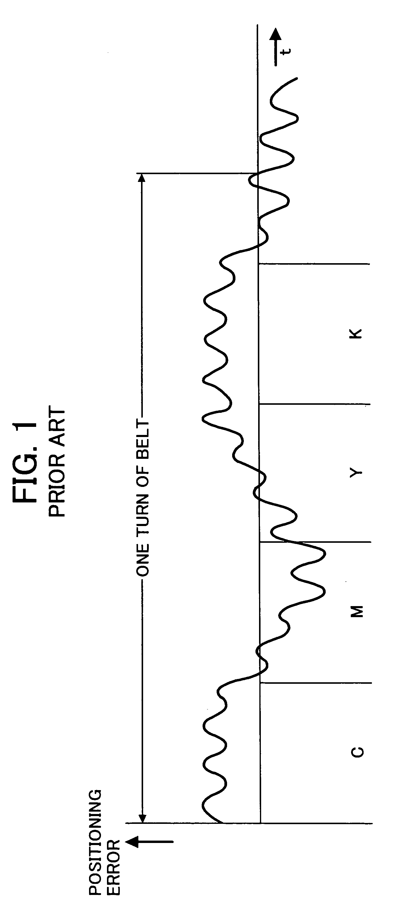
[0037]Reference will be made to FIGS. 4 through 10 for describing a preferred embodiment of the present invention in which a mark sensing device is applied to an image forming apparatus. As shown in FIG. 4, the image forming apparatus, generally 1, is implemented as a tandem, color image forming apparatus including a belt or turnable body 3 for conveying a paper sheet or similar recording medium by way of example. Electronic process units 1K (black), 1M (magenta), 1Y (yellow) and 1C (cyan) are sequentially arranged in this order from the upstream side in a direction in which the belt 3 turns, i.e., it conveys a paper sheet.

[0038]The electronic process units (simply process units hereinafter) 1K, 1M, 1Y and 1C, playing the role of an image forming unit each, are configured to form a black, a magenta, a cyan and a yellow toner image, respectively. Because the process units 1K through 1C are identical in configuration with each other except for the color of an image to form, let the fo...

second embodiment

[0068]Referring to FIG. 11, an alternative embodiment of the present invention will be described which is essentially similar to the first embodiment described above except for the following. In the illustrative embodiment, parts and elements identical with those of the first embodiment are designated by identical reference numerals and will not be described specifically in order to avoid redundancy. Let the following description concentrate on arrangements unique to the illustrative embodiment.

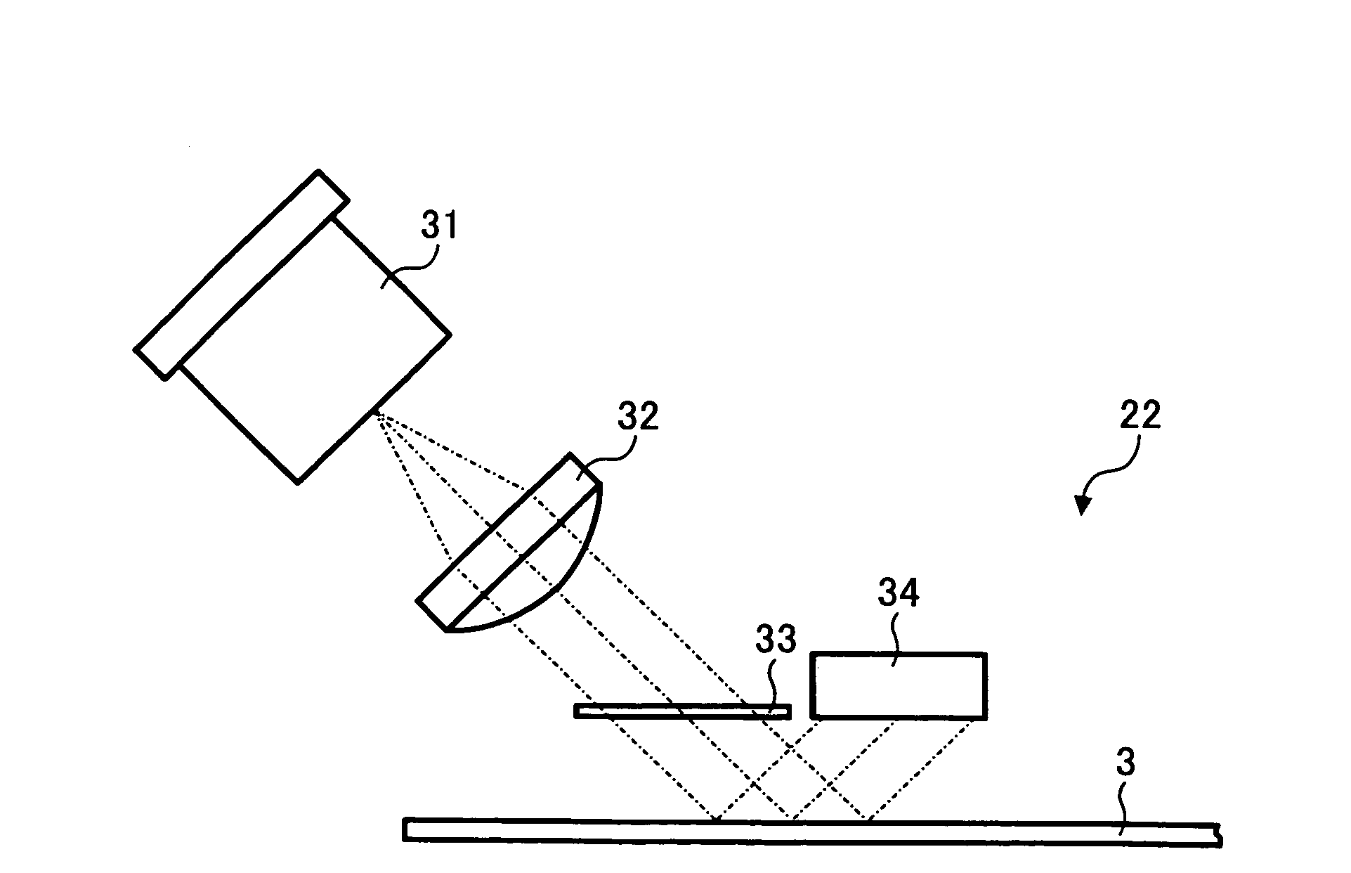
[0069]As shown in FIG. 11, a mark sensor 51 also includes the light source 31 for emitting a light beam, the lens 32 for condensing the light beam emitted from the light source 31 on the scale 21, and the slit mask 33 for shaping the light beam output from the lens 32 with the slits 33a, see FIGS. 7A and 7B or 8A and 8B. In the illustrative embodiment, the mark sensor 51 further includes a deflector 52 for deflecting light passed through the slit mask 33 and then reflected and scattered by th...

third embodiment

[0072]FIGS. 12 and 13 show another alternative embodiment of the present invention which is essentially similar to the first embodiment except for the following. In the illustrative embodiment, parts and elements identical with those of the first embodiment are designated by identical reference numerals and will not be described specifically in order to avoid redundancy. Let the following description concentrate on arrangements unique to the illustrative embodiment.

[0073]FIG. 12 shows a slit mask included in the illustrative embodiment while FIG. 13 shows electric signals output from the light-sensitive device. As shown in FIG. 12, the slit mask 33 is formed with twelve slits 33a in total in four consecutive regions A, B, *A and *B each of which is shifted from adjoining one by one-fourth of the mark period. More specifically, three of the twelve slits 33a are shifted from nearby three by one-fourth of the mark period. In this configuration, the light beam is divided by the slit mas...


PUM


Abstract

A mark sensing device of the present invention senses marks formed on a turnable body in a preselected periodic pattern in a direction of movement of the turnable body with light emitted from a light source. A slit mask is formed with slits for splitting the light emitted from the light source. A light receiving portion receives the light thus split and then incident on the mark. The slits of the slit mask each belong to either one of two regions one of which is shifted from the other by one-half of the period of the periodic pattern. The light receiving portion receives the light incident on the mark in each of the two regions and converts the light received to two electric signals. A control signal for controlling the amount of movement of the turnable body is produced from the two electric signals.

Description

BACKGROUND OF THE INVENTION[0001]1. Field of the Invention[0002]The present invention relates to a mark sensing device, a device for driving a turnable body and an image forming apparatus.[0003]2. Description of the Prior Art[0004]Today, an image forming apparatus of the type including a photoconductive belt, intermediate image transfer belt or similar turnable body for image formation is extensively used. A prerequisite with this type of image forming apparatus is that the amount of turn or movement of the turnable body be controlled accurately enough to precisely position an image on the turnable body or a recording medium being conveyed by the turnable body. In practice, however, the amount of turn of the turnable body often varies due to some cause and makes it difficult to reduce the shift of an image position. Particularly, in a color image forming apparatus, a change in the amount of rotation prevents images of different colors from being registered at a preselected position,...

Claims


Application Information

Patent Timeline
Patent Type & Authority Patents(United States)
IPC IPC(8): G03G15/00
CPCG03G15/1605G03G15/50G03G2215/00139G03G2215/0158
Inventor KUDO, KOICHITAKAYAMA, HIDEYUKI
Owner RICOH KK
Why Eureka
Try Eureka