Operation monitoring and enhanced host communications in systems employing electronic article surveillance and RFID tags

a technology of electronic article surveillance and host communication, applied in the direction of burglar alarm mechanical actuation, instrumentation, electromagnetic radiation sensing, etc., can solve the problems of false alarming of the eas system which is undesirable, poor quality or damage of the tag, and improper use of the eas

Active Publication Date: 2009-05-05
DATALOGIC SCANNING +1
View PDF102 Cites 69 Cited by
  • Summary
  • Abstract
  • Description
  • Claims
  • Application Information

AI Technical Summary

Benefits of technology

[0016]Another aspect of the invention is directed to host notification of various EAS events. EAS event notifications preferably are sent to the POS using special, reserved barcodes as this technique can be implemented without changing the existing communication channel between the scanner and the POS or other host.

Problems solved by technology

This failure to deactivate can result in false alarming of the EAS system which is undesirable.
Performance deficiencies in deactivating an EAS tag may result from any of several causes, such as poor quality or damaged tags, improper use of the EAS deactivation equipment, improper placement of the EAS tag on the item, or degraded performance in the deactivation equipment.
However, this procedure presents a security risk as a tag manually deactivated may not be the one attached to the item just scanned.
In addition, other EAS activities can provide important input to system software, for example in the host or POS, but reconfiguring the interface between the scanner and a POS terminal to communicate real-time EAS activities is complicated and costly.
RFID tags and hybrid / combination RFID / EAS tags may also experience performance deficiencies as a result of several causes, such as poor quality or damaged RFID tags, improper use of the RFID reading equipment, improper placement of the tags, or degraded performance in the reading equipment.

Method used


Image

  • Operation monitoring and enhanced host communications in systems employing electronic article surveillance and RFID tags
  • Operation monitoring and enhanced host communications in systems employing electronic article surveillance and RFID tags
  • Operation monitoring and enhanced host communications in systems employing electronic article surveillance and RFID tags

Examples


first embodiment

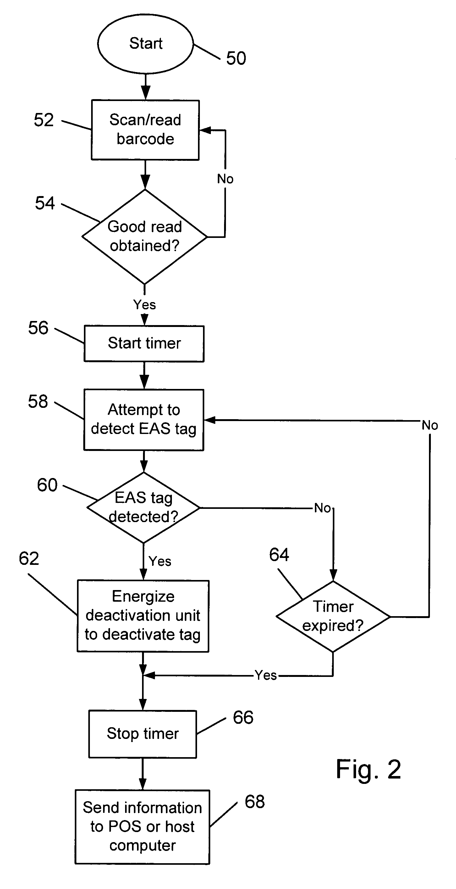
[0035]FIG. 2 is a flow chart of a method as described in the following steps.[0036]Activating the system at start step 50.[0037]Commencing reading a barcode entering the scan volume at step 52.[0038]Determining at step 54 whether a good read of the barcode has been obtained; if “No” continue scanning at step 52 and if “Yes” proceed to step 56.[0039]Starting timer at step 56.[0040]Attempting to detect an EAS tag at step 58.[0041]Determining at step 60 whether an EAS tag has been detected within a time limit. If no tag is detected, it is queried at step 64 whether the time limit has expired: if “No” (time limit has not expired) continue detecting at step 58; if “Yes” (time limit has expired) proceeding to step 66. If an EAS tag is detected at step 60, proceed to step 62.[0042]At step 62, energizing the deactivation unit to deactivate the tag.[0043]Stopping the timer at step 66.[0044]At step 68, sending the operative information to the POS or host computer.

[0045]In a first instance, t...

second embodiment

[0049]FIG. 3 is a flow chart of a method as described in the following steps.[0050]Activating the system at start step 150.[0051]Commencing reading a barcode entering the scan volume at step 152.[0052]Determining at step 154 whether a good read of the bar code has been obtained; if “No” continue scanning at step 152 and if “Yes” proceed to step 156.[0053]Starting timer #1 at step 156.[0054]Attempting to detect an EAS tag at step 158.[0055]Determining at step 160 whether an EAS tag has been detected within a time limit. If no tag is detected, it is queried at step 164 whether the time limit has expired: if “No” (time limit has not expired) continue detecting at step 158; if “Yes” (time limit has expired) proceeding to step 166 stopping timer #1 and then proceeding to step 178. If an EAS tag is detected at step 160, proceed to step 162.[0056]At step 162, stopping timer #1 and starting timer #2 and then proceeding to step 168.[0057]Energizing the deactivation unit to deactivate the ta...

third embodiment

[0063]In some systems, the data reader and the EAS system are not integrated or connected to the extent as presumed by the methods of FIGS. 2 and 3. FIG. 4 is a flow chart for a third embodiment where the data reader and the EAS system are not integrated but merely communicate with each other, by the following steps.[0064]Activating the system at start step 200. Scanning and EAS detection proceed at the same time along parallel / separate paths.

In the scanner path:[0065]Commencing reading a barcode entering the scan volume at step 202.[0066]Determining at step 204 whether a good read of the bar code has been obtained; if “No” continue scanning at step 202 and if “Yes” proceed to step 206.[0067]Starting timer at step 206; and at step 214 sending an arming signal to the EAS system; then proceeding to step 208.[0068]At the same time as scanning occurs, the EAS system receives the start signal and attempts to detect an EAS tag at step 220.[0069]Determining at step 222 whether an EAS tag h...


PUM


Abstract

A system and method for monitoring operation and performance of electronic tags such as article surveillance (EAS) tags or radio frequency identification (RFID) tags such as by monitoring and reporting electronic tag readability and operator / system performance levels. The system includes an optical symbol reader and / or electronic tag sensor / deactivator that measures and reports values of reading, detection, or deactivation events during operation which may be indicative of electronic tag operability. The apparatus may further comprise a data accumulation device including memory storage to accumulate the measurement values for each set of electronic tags, and a programmed computing system to analyze the measured values and report on the results of the analysis.

Description

RELATED APPLICATIONS[0001]This application is a continuation-in-part of U.S. application Ser. No. 10 / 390,542 filed Mar. 14, 2003, which claims priority from U.S. Provisional Application No. 60 / 365,432 filed Mar. 18, 2002, both applications incorporated herein by this reference.BACKGROUND OF THE INVENTION[0002]The field of the present invention relates to monitoring methods and techniques for systems employing electronic article surveillance (EAS) tags or radio frequency identification (RFID) tags. In particular, methods and apparatus are described herein for monitoring performance and effectiveness of EAS deactivations systems and RFID readers. In addition, improved host communications are disclosed.[0003]Many retail checkout and inventory control systems employ RFID readers or EAS tag deactivation devices. Electronic article surveillance (EAS) systems have employed either reusable EAS tags or disposable EAS tags to detect articles for prevention of shoplifting and unauthorized remo...

Claims


Application Information

Patent Timeline
Patent Type & Authority Patents(United States)
IPC IPC(8): G06F19/00G06K15/00G06K5/00G06Q30/00G06Q40/00G06Q90/00G07D11/00G08B13/14G06K17/00G07G1/12
CPCG06K17/0022G07G1/009G07G1/12G07G3/00G06K2017/0051
Inventor SALIM, MOHAMED ARIFCLIFFORD, HAROLD C.GUESS, ALAN JACKSONPARIS, BRUCE EDWARD
Owner DATALOGIC SCANNING
Why Eureka
Try Eureka