Spring spacer for a spring

a spring and spacer technology, applied in the field of spring spacers, can solve the problems of affecting the quality of springs, prone to wear and lower durability, and movement of shoulder surfaces relative, so as to improve manufacturing productivity, reduce wear and durability, and improve durability

Inactive Publication Date: 2009-05-05
YAMAHA MOTOR CO LTD
View PDF19 Cites 9 Cited by
  • Summary
  • Abstract
  • Description
  • Claims
  • Application Information

AI Technical Summary

Benefits of technology

[0016]An aspect of the present invention is directed toward addressing one or more of these problems and provide a spring spacer having a simple structure that prevents contact between an end of a first turn and a second turn of a spring. Preferably, the spring is made of a material having a low surface hardness, such as Ti or the like. A spring spacer, which is configured in accordance with the embodiments disclosed herein, improves the durability of the spring and is easily mounted to the spring so as to improve productivity.
[0033]In certain embodiments, the spring spacer is a simple structure that prevents contact between an end of a first turn and a second turn of a spring, which may be Ti or the like having a low surface hardness, to enable achieving an improvement in durability.
[0034]In certain embodiments, the holding portion has a shape so as not to contact the spring bearing surface and the spring all the time. The spring spacer can be mounted to the spring during initial assembly or retrofitted to the spring by press fitting or engagement so as to improve manufacturing productivity.
[0035]Accordingly, when the spring spacer is used for a spring that forms various units, or a suspension spring that forms a suspension unit of a vehicle, it is possible to prevent contact abrasion to a second turn of the spring, the suspension spring, the unit, the suspension unit, and the vehicle, and to also improve productivity.

Problems solved by technology

While Ti springs are advantageously lightweight, they are prone to wear and have a lower durability due to their low surface hardness.
Due to their low durability, Ti springs are often replaced after 1 or 2 races of a motorcycle.
However, the clearance may permit the spring seat to rotate during assembly of the suspension unit and cause movement of the shoulder surface relative to the suspension spring.
However, this additional step may decrease productivity.
However, this matching process of temporarily mounting the different height spring seats with each spring and selecting an optimum spring seat for the spring may decrease productivity.
On the other hand, in the case where an end of a first turn of a suspension spring is insert-molded in a spring seat made of a synthetic resin, the problem described above is overcome but the molding process of the spring seat in a large-sized suspension spring is complex and may decrease productivity.

Method used


Image

  • Spring spacer for a spring
  • Spring spacer for a spring
  • Spring spacer for a spring

Examples


first embodiment

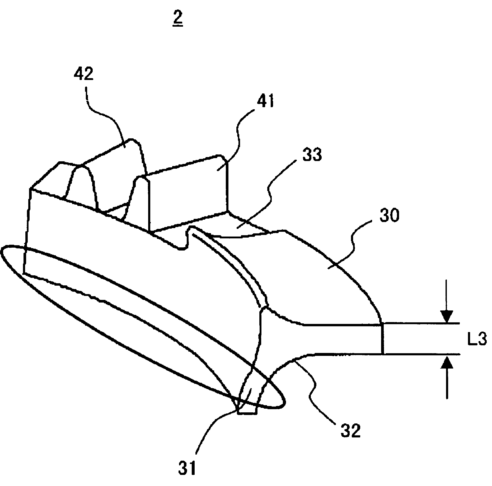
[0042]FIG. 3 is a perspective view showing a spring spacer and for use with the suspension unit illustrated in FIG. 2A.

[0043]FIG. 4A is a perspective view of the spring spacer in a first interim position and between a first turn and a second turn of the spring illustrated in FIG. 2B.

[0044]FIG. 4B is a perspective view of the spring spacer in a second interim position and between the first turn and the second turn of the spring illustrated in FIG. 2B.

[0045]FIG. 4C is a perspective view of the spring spacer in a mounted position to the spring.

[0046]FIG. 5 is a plan view of the spring spacer in the mounted position illustrated in FIG. 4C.

[0047]FIG. 6A is a front view of the spring spacer in the mounted position illustrated in FIG. 4C.

[0048]FIG. 6B is a left side view of the spring spacer in the mounted position illustrated in FIG. 4C.

[0049]FIG. 6C is a right side view of the spring spacer in the mounted position illustrated in FIG. 4C.

[0050]FIG. 6D is a front view of the spring spacer...

second embodiment

[0051]FIG. 7 is a perspective view showing a spring spacer according to the invention.

[0052]FIG. 8A is a perspective view of the spring spacer illustrated in FIG. 7 in a first interim position and between a first turn and a second turn of the spring illustrated in FIG. 2B.

[0053]FIG. 8B is a perspective view of the spring spacer illustrated in FIG. 7 in a mounted position to the spring.

[0054]FIG. 9 is a plan view of the spring spacer in the mounted position illustrated in FIG. 8B.

[0055]FIG. 10A is a front view of the spring spacer in the mounted position illustrated in FIG. 8B.

[0056]FIG. 10B is a left side view of the spring spacer in the mounted position illustrated in FIG. 8B.

[0057]FIG. 10C is a right side view of the spring spacer in the mounted position illustrated in FIG. 8B.

[0058]FIG. 10D is an enlarged view of the spring spacer and an upper portion of the spring from FIG. 10C.

third embodiment

[0059]FIG. 11 is a perspective view showing a spring spacer according to the invention.

[0060]FIG. 12A is a perspective view of the spring spacer illustrated in FIG. 11 in a first interim position and between a first turn and a second turn of the spring illustrated in FIG. 2B.

[0061]FIG. 12B is a perspective view of the spring spacer illustrated in FIG. 11 in a second interim position and between the first turn and the second turn of the spring illustrated in FIG. 2B.

[0062]FIG. 12C is a perspective view of the spring spacer in a mounted position to the spring.

[0063]FIG. 13 is a plan view of the spring spacer in the mounted position illustrated in FIG. 12C.

[0064]FIG. 14A is a front view of the spring spacer in the mounted position illustrated in FIG. 12C.

[0065]FIG. 14B is a left side view of the spring spacer in the mounted position illustrated in FIG. 12C.

[0066]FIG. 14C is a right side view of the spring spacer in the mounted position illustrated in FIG. 12C.


PUM


Abstract

A spring spacer is provided to improve the durability of a spring, which is made of Ti or the like and low in surface hardness, by preventing abrasion With the spring spacer placed between a first turn and a second turn of a Ti spring, the spring spacer prevents an end of the first turn from contacting the second turn. The spring spacer includes a contact preventive portion that is interposed between the first turn and the second turn of the Ti spring to prevent the end of the first turn from contacting with the second turn. A holding portion holds the contact preventive portion on the spring or the spring bearing surface. The spring spacer can be used in a variety of applications, including on vehicle suspension springs, engine valve spring, and similar lightweight springs.

Description

RELATED APPLICATIONS[0001]The present application is based on and claims priority under 35 U.S.C. § 119 to Japanese Patent Application No. 2005-106918, filed on Apr. 1, 2005; and Japanese Patent Application No. 2004-364417, filed Dec. 16, 2004, the entire contents of which are hereby expressly incorporated by reference herein.BACKGROUND OF THE INVENTION[0002]1. Field of the Invention[0003]The present invention relates to a spring spacer for use with a spring of a suspension system for a vehicle. Preferably, the spring is made of a material such as Ti or the like, and has a low surface hardness.[0004]2. Description of the Related Art[0005]In recent years, motorcycles used for specific applications such as racing or the like utilize springs made of Titanium (Ti). Springs made of Ti are lightweight as compared to conventional springs made of Iron (Fe). For example, a suspension unit that has a Ti spring may weigh 200 to 500 g (by spring constant) less than a suspension unit that utiliz...

Claims


Application Information

Patent Timeline
Patent Type & Authority Patents(United States)
IPC IPC(8): F16F1/13
CPCF16F1/126F16F1/13
Inventor OOHASHI, SATOSHI
Owner YAMAHA MOTOR CO LTD
Why Eureka
Try Eureka