Compact devices for generating pure hydrogen
a compact device and pure hydrogen technology, applied in catalyst activation/preparation, combustible gas production, bulk chemical production, etc., can solve the problems of insufficient energy storage capacity of storage or rechargeable batteries, inability to provide compressed hydrogen, and inability to meet the needs of certain applications
- Summary
- Abstract
- Description
- Claims
- Application Information
AI Technical Summary
Problems solved by technology
Method used
Image
Examples
example 1
Hydrogen Flux Through a Reformer Sub Assembly in which the Membrane is Supported on a Sintered Porous Metal Substrate
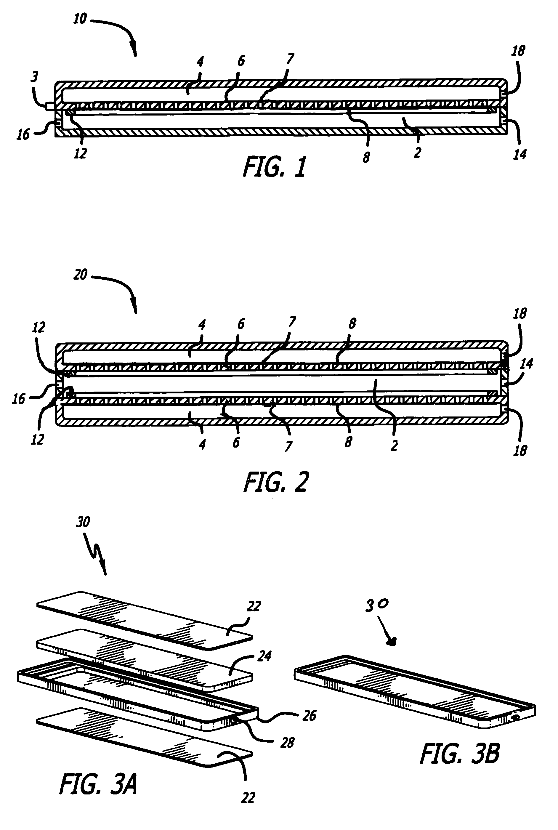
[0162]A gas mixture consisting of hydrogen and nitrogen in the nominal volumetric ratio of 75% H2 and 25% N2 and at a nominal flow rate of 1500 sccm was fed into a reaction chamber as shown in FIG. 1 after heating the chamber to about 450° C. The reaction sub assembly was constructed of SS 304. The membrane consisted of a Pd / Ag foil of nominal composition 75% Pd / 25% Ag and had a surface area of 23 cm2.
[0163]The membrane foil, 25 microns in nominal thickness, was supported on a sintered porous stainless steel 316L substrate that possessed a nominal porosity of 41% (Mott Corp). The reactor sub assembly was placed in a Watlow electrical furnace which allowed for increasing the temperature of the furnace using a suitable temperature controller (Omega). The reaction chamber contained a 40 ppi FeCrAlY metal foam substrate to provide uniform flow and heat distribution.
[0164]...
example 2
Hydrogen Flux Through a Reactor Sub Assembly in which the Membrane was Supported on a Solid Plate Containing Perforations
[0166]The test as described in Example 1 was repeated using reactor sub assemblies that were identical to that used in Example 1, except for the fact that the membrane foil was supported on a solid SS 304 plate that contained small evenly spaced holes 1 / 32″ diameter with a total exposed surface area of 0.23 in2. In particular, hydrogen flux (sccm / cm2) was passed at 600° C. and at a nominal pressure of 5.8 bar through two identically construed Units 1 and 2, at various temperature cycles. Each temperature cycle was between ambient temperature and 600° C.
[0167]The pressure on the permeate side of the membrane was maintained at atmospheric pressure. The results reported in FIG. 27 show an approximately 30% decrease in hydrogen flux was observed with time. The membrane was found to be very stable to thermal cycling between ambient temperature and 600° C., as no decrea...
example 3
Hydrogen Flux Through a Reactor Sub Assembly in which the Membrane was Supported on a Sintered Porous Substrate
[0168]The substrate also behaved as a flow channel for transport of hydrogen to the exit ports of the device.
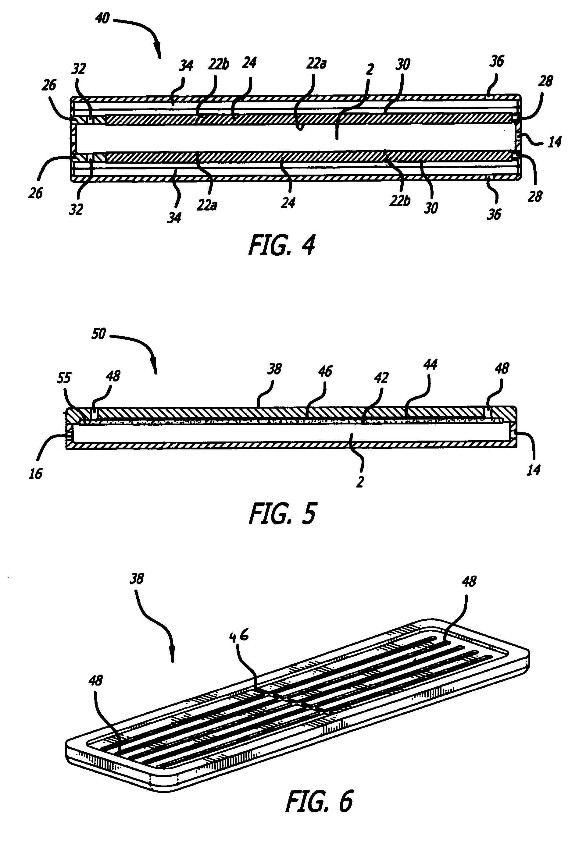
[0169]A gas mixture consisting of hydrogen and nitrogen in the nominal volumetric ratio of 75% H2 and 25% N2 and at a nominal flow rate of 3600 sccm was fed the reactor sub assembly as shown in FIG. 5 after heating the reactor to about 450° C. The reactor sub assembly was constructed of 304L stainless steel. The membrane consisted of a Pd / Ag foil of nominal composition 75% Pd / 25% Ag and had a surface area of 55 cm2. The membrane foil was supported on a sintered porous 316 stainless steel substrate that possessed a nominal porosity of 41% (Mott Corp). The membrane reactor was placed in a Watlow electrical furnace which allowed for increasing the temperature of the furnace using a suitable temperature controller (Omega). The reaction chamber contained a 40 ppi Inconel®...
PUM
| Property | Measurement | Unit |
|---|---|---|
| thicknesses | aaaaa | aaaaa |
| thickness | aaaaa | aaaaa |
| temperatures | aaaaa | aaaaa |
Abstract
Description
Claims
Application Information
 - R&D
- Intellectual Property
- Life Sciences
- Materials
- Tech Scout
- Unparalleled Data Quality
- Higher Quality Content
- 60% Fewer Hallucinations
Browse by: Latest US Patents, China's latest patents, Technical Efficacy Thesaurus, Application Domain, Technology Topic, Popular Technical Reports.
© 2025 PatSnap. All rights reserved.Legal|Privacy policy|Modern Slavery Act Transparency Statement|Sitemap|About US| Contact US: help@patsnap.com


