
Backlight for liquid crystal display

a liquid crystal display and backlight technology, applied in the direction of instruments, lighting and heating apparatus, planar/plate-like light guides, etc., can solve the problem of poor 3d image quality, and achieve the effect of reducing visual cross-talk

Inactive Publication Date: 2009-05-05
3M INNOVATIVE PROPERTIES CO
View PDF11 Cites 222 Cited by
  • Summary
  • Abstract
  • Description
  • Claims
  • Application Information

AI Technical Summary

Benefits of technology

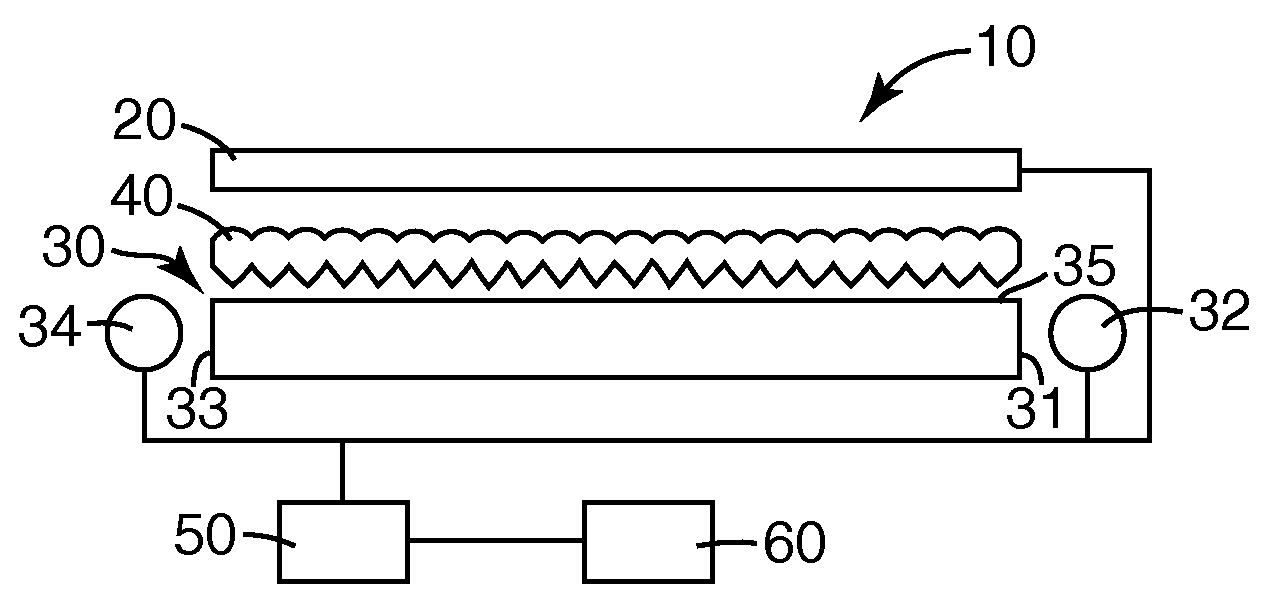
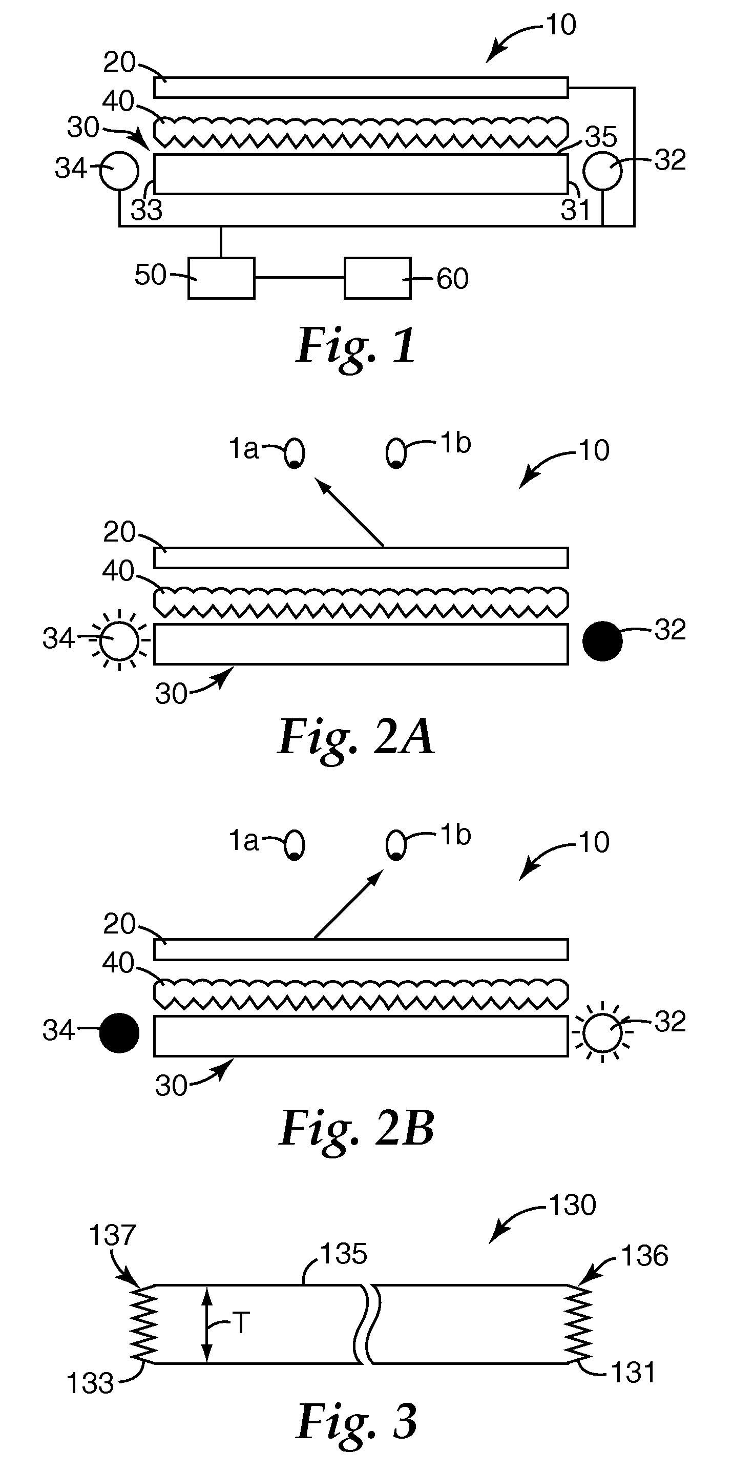
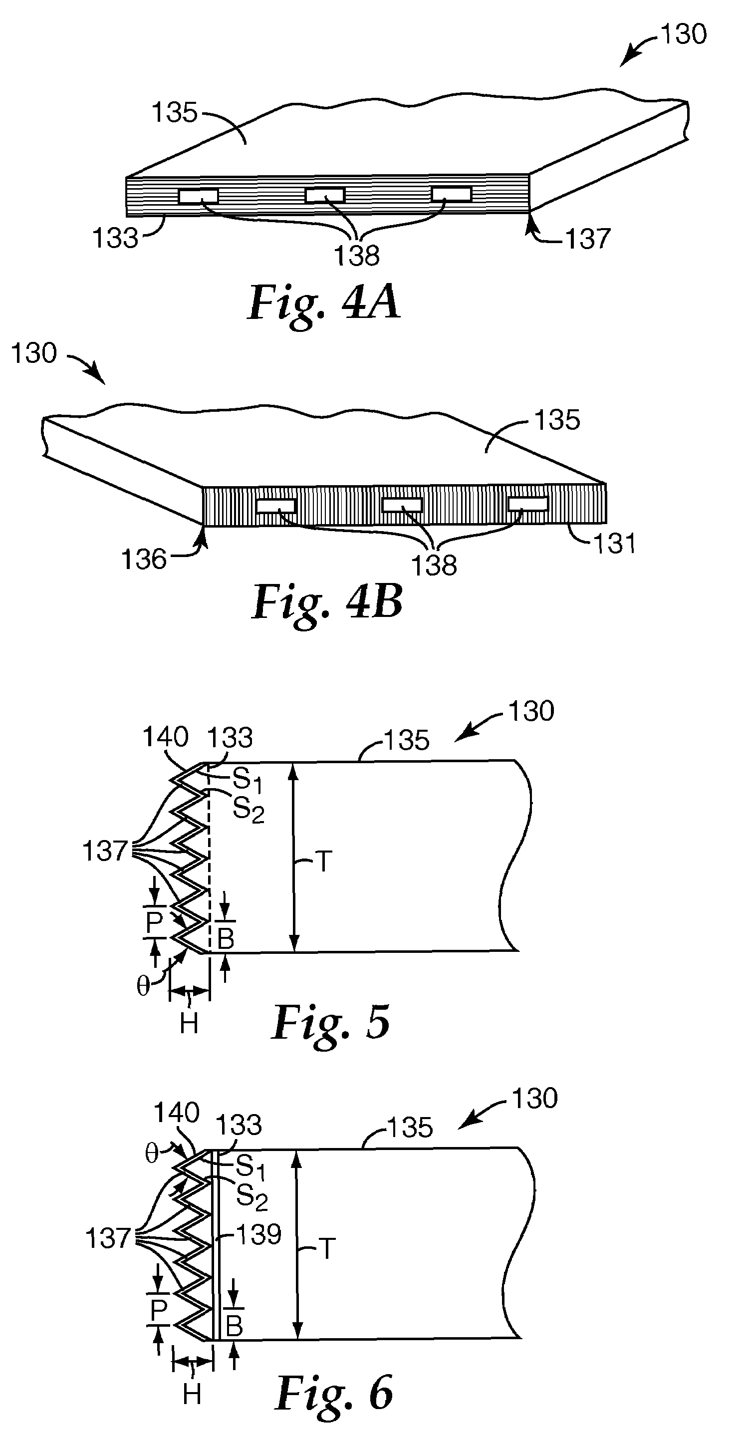
The present disclosure relates to a backlit liquid crystal display apparatus that reduces visual cross-talk between displayed left eye and right eye images. The technical effect of the patent is to provide a backlight that improves the image quality of the display by reducing the interference between left and right eye images. This is achieved by using a lightguide with antireflection features on its surface that reflect light in a way that reduces glare and improves the sharpness of the display. The antireflection features have a specific design that minimizes the impact on the display image and ensures that the display looks good from different viewing angles.

Problems solved by technology

Further, if the left and right sources provide alternating illumination of a directional backlight structure which extracts light based on the light source end when the right eye image light input surface opposes a left eye image light input surface, light entering either surface can subsequently reflect off the opposing surface and create visual confusion between the left eye image and right eye image or equivalently cross-talk between left eye and right eye images resulting in poor 3D image quality.

Method used


Image

  • Backlight for liquid crystal display
  • Backlight for liquid crystal display
  • Backlight for liquid crystal display

Examples


Embodiment Construction

[0018]In the following description, reference is made to the accompanying drawings that form a part hereof, and in which are shown by way of illustration several specific embodiments. It is to be understood that other embodiments are contemplated and may be made without departing from the scope or spirit of the present invention. The following detailed description, therefore, is not to be taken in a limiting sense.

[0019]All scientific and technical terms used herein have meanings commonly used in the art unless otherwise specified. The definitions provided herein are to facilitate understanding of certain terms used frequently herein and are not meant to limit the scope of the present disclosure.

[0020]Unless otherwise indicated, all numbers expressing feature sizes, amounts, and physical properties used in the specification and claims are to be understood as being modified in all instances by the term “about.” Accordingly, unless indicated to the contrary, the numerical parameters s...


PUM

PropertyMeasurementUnit
aspect ratioaaaaaaaaaa
frame response timeaaaaaaaaaa

Abstract

A backlight includes a lightguide having a light emission surface, a first light input surface, a second light input surface opposing the first light input surface, and a lightguide thickness. A plurality of antireflection features are on or in the first light input surface and second light input surface. Each antireflection feature has a base length value and a height value that are less than the light guide thickness. A right eye image solid state light source is positioned to provide light into the first light input surface and a left eye image solid state light source is positioned to provide light into the second light input surface.

Description

FIELD[0001]The present disclosure relates to a backlit liquid crystal display and particularly to a backlight for a liquid crystal display that reduces visual cross-talk between displayed left eye and right eye images.BACKGROUND[0002]A stereoscopic display usually presents an observer with images with parallax from individual right and left eye viewpoints. There are two methods of providing the two eyes of the observer with the parallax images. In one method, the observer utilizes a pair of shutter or 3D glasses which transmit or block light from the viewer's eyes in synchronization with alternating the left / right image display. Similarly, in another method, right eye and left eye viewpoints are alternatively displayed and led to the respective eyes of the observer but without the use of 3D glasses. This second method is referred to as autostereoscopic and is desired for stereo 3D viewing because separate glasses are not needed.[0003]A liquid crystal display (LCD) is a sample and ho...

Claims


Application Information

Patent Timeline
Patent Type & Authority Patents(United States)
IPC IPC(8): G02F1/1335
CPCG02B6/0016G02B6/0053G02B6/0068G02B27/2264G02B30/24G02F1/1335
Inventor SCHULTZ, JOHN C.BROTT, ROBERT L.SYKORA, MICHAEL J.
Owner 3M INNOVATIVE PROPERTIES CO
Learn More