Optical near-field generator and recording apparatus using the optical near-field generator

a generator and near-field technology, applied in the field of optical recording, can solve problems such as weak optical near, and achieve the effect of lessening the influence of optical near-field

Inactive Publication Date: 2009-05-05
HITACHI LTD
View PDF11 Cites 47 Cited by
  • Summary
  • Abstract
  • Description
  • Claims
  • Application Information

AI Technical Summary

Benefits of technology

[0011]It is the object of this invention to lessen influence of the optical near-fields generated at the parts except for the point at which the intense optical near-field is generated.

Problems solved by technology

Unfortunately, weak optical near-fields are also generated at these vertices 13.

Method used


Image

  • Optical near-field generator and recording apparatus using the optical near-field generator
  • Optical near-field generator and recording apparatus using the optical near-field generator
  • Optical near-field generator and recording apparatus using the optical near-field generator

Examples


embodiment 1

[0118](Embodiment 1)

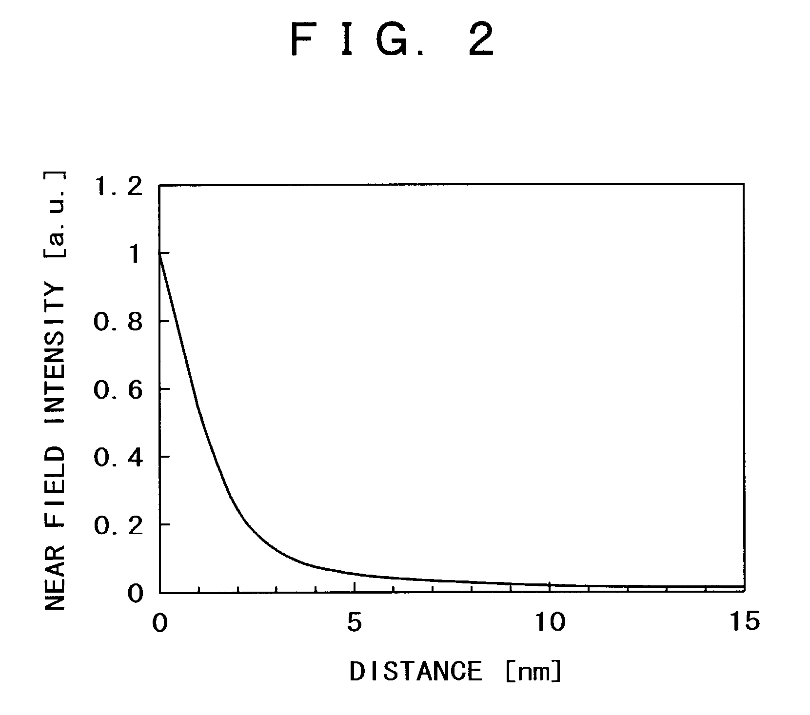
[0119]An optical near-field generator of this invention is composed of a planar scatterer 21 such that an intense optical near-field 25 is generated at a vertex 22 thereof, and a substrate 24 that supports it, as shown in FIGS. 3A and 3B. The planar scatterer is arranged so that a direction of a plane of the scatterer becomes substantially parallel to the surface of a sample or recording medium 27, and the surface of the scatterer is etched away so that etching depth d from the surface becomes not less than the penetration depth of optical near-field at the parts except for the vicinity of the vertex 22 where the intense optical near-field is generated (surroundings 26 of vertices or an edge 23 on the opposite side). In other words, the surface of the scatterer is separated by a distance d not less than the penetration depth of optical near-field from the recording medium 27 at the parts except for the vicinity of the vertex 22 that is intended to generate the op...

embodiment 2

[0137](Embodiment 2)

[0138]The embodiment 2 shows an embodiment for preventing wearing of the scatterer.

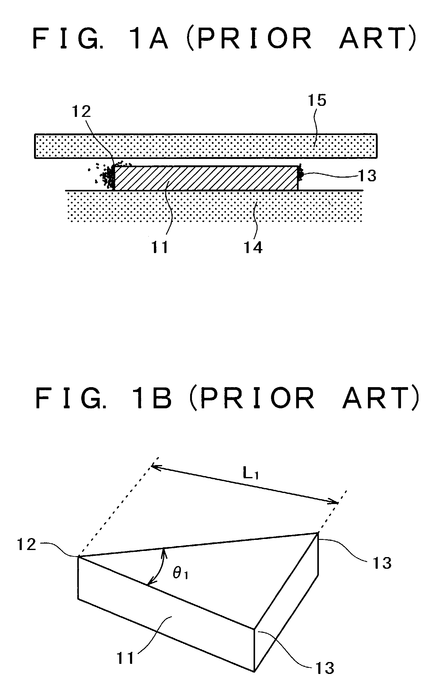
[0139]In the case where the above-mentioned planar scatterer arranged so that the surface thereof is substantially parallel to the medium surface is used to measure an uneven sample, it is preferable that the scatterer is formed on the substrate surface, as shown in FIGS. 3A and 3B. This is because the vertex 22 where an optical near-field is generated can easily come into a recessed part. However, the vertex 22 tends to wear in this case. To prevent this, it is advisable that as shown in FIG. 21A, side faces of the scatterer in the vicinity of a vertex 181 are covered with a material of high hardness. Here, the vicinity of the vertex 18 is defined as a range located within 50 nm from the vertex 181. In this embodiment, a scatterer that had a length L1 of 150 nm, an angle θ1 of 60 degrees, a thickness t1 of 30 nm, whose material was gold, whose shape was a triangle, and whose surfa...

embodiment 3

[0141](Embodiment 3)

[0142]The embodiment 3 shows an example in which the scatterer is arranged perpendicular to the surface of the sample or medium.

[0143]In the case where the planar scatterer arranged so that the surface thereof is perpendicular to the surface of the sample or medium is used to measure a sample having an uneven surface, it is preferable that a vertex 191 at which the optical near-field is generated is shaped so as to protrude from a substrate surface 192, as shown in FIGS. 22A, 22B, and 22C. This is because the vertex 191 can easily come into a recessed part. However, if the vertex 191 is protruded as described above, the scatterer may contact with the sample and be broken easily. To prevent this, it is preferable to cover the side faces of the scatterer with a material of high hardness as explained in the embodiment 2. In this embodiment, a scatterer of a rectangular shape that had a short-side length of 20 nm, the long-side length of 150 nm, and the width t1 of 3...


PUM

PropertyMeasurementUnit
wavelengthaaaaaaaaaa
angleaaaaaaaaaa
angleaaaaaaaaaa

Abstract

A near-field optical probe and optical near-field generator are provided. A problem of a probe having a scatterer in which optical near-field noises are generated at the parts other than for a point at which an intense optical near-field is generated, is solved. In one example of the probe, a surface of the parts except for a vertex of the scatterer at which the intense optical near-field is generated is etched so that an etching depth becomes not less than a penetration depth of the optical near-field. The probe facilitates control of noises when a sample is observed or recording marks are reproduced.

Description

COPYRIGHT NOTICE[0001]A portion of the disclosure of this patent document contains material which is subject to copyright protection. The copyright owner has no objection to the facsimile reproduction by anyone of the patent document or the patent disclosure, as it appears in the Patent and Trademark Office patent file or records, but otherwise reserves all copyright rights whatsoever.BACKGROUND OF THE INVENTION[0002]1. Field of the Invention[0003]This invention generally relates optical recording and, more particularly, to a near-field optical probe and an optical near-field generator that generates an optical near-field.[0004]2. Discussion of Background[0005]In recent years, a probe that uses a planar metal scatterer has been proposed for optical recording. This is a probe in which a planar metal scatterer 351 in the shape of a triangle is formed on a flat substrate, as shown in FIGS. 43A and 43B. FIG. 43A shows a probe in which a single metal scatterer 351 is formed, and FIG. 43B...

Claims


Application Information

Patent Timeline
Patent Type & Authority Patents(United States)
IPC IPC(8): G11B11/00G01Q60/22G01Q80/00G01Q90/00G03F7/20G11B5/00G11B5/02G11B5/127G11B5/39G11B7/12G11B7/122G11B7/135G11B7/1387G11B7/22G11B9/00G11B11/105
CPCB82Y10/00B82Y20/00B82Y35/00G01Q60/22G01Q70/12G03F7/70383G11B5/127G11B5/1278G11B7/122G11B7/1387G11B7/22G11B9/14G11B9/1409B82Y15/00G11B5/314B82Y25/00G01Q80/00G11B5/3967G11B11/10554G11B11/1058G11B2005/0002G11B2005/0005G11B2005/3996G11B2005/0021
Inventor MATSUMOTO, TAKUYASAGA, HIDEKI
Owner HITACHI LTD
Why Eureka
Try Eureka