
Multiprocessing systems employing hierarchical spin locks

Active Publication Date: 2009-05-05
ORACLE INT CORP
View PDF16 Cites 15 Cited by
  • Summary
  • Abstract
  • Description
  • Claims
  • Application Information

AI Technical Summary

Benefits of technology

[0014]Various embodiments of multiprocessing computer systems and methods are provided that implement hierarchical spin locks. In one embodiment, a method for controlling a software lock acquirable by processors in a plurality of nodes of a multiprocessing system is disclosed. The method comprises a first processor of a first node of the plurality of nodes acquiring the lock, and the first processor selectively releasing the lock in a first s

Problems solved by technology

Many distributed shared memory architectures have non-uniform access time to the shared memory.
One particular problem associated with multiprocessing computer systems having distributed shared memory architectures relates to spin-lock operations.
Although simple spin-lock implementations can create very bursty traffic as described below, they are still the most commonly used software lock within computer systems.
Since only one of the spinning processors will acquire the lock during such contention, the failed test-and-set operations of the remaining processors result in undesirable requests on the network.
Due to this, the latency associated with the release of a lock until the next contender can acquire the lock may be relatively high.
In addition, the large number of transactions can further limit the maximum frequency at which ownership of the lock can migrate from processor to processor and node to node.
This may result in yet additional undesirable network traffic.
While the various optimizations for spin-lock implementations have in some instances led to enhanced performance, most solutions do not consider or exploit the NUCA characteristics of a distributed shared memory computer system.
In addition, many implementations have resulted in relatively high latencies for uncontended locks.

Method used


Image

  • Multiprocessing systems employing hierarchical spin locks
  • Multiprocessing systems employing hierarchical spin locks
  • Multiprocessing systems employing hierarchical spin locks

Examples


Embodiment Construction

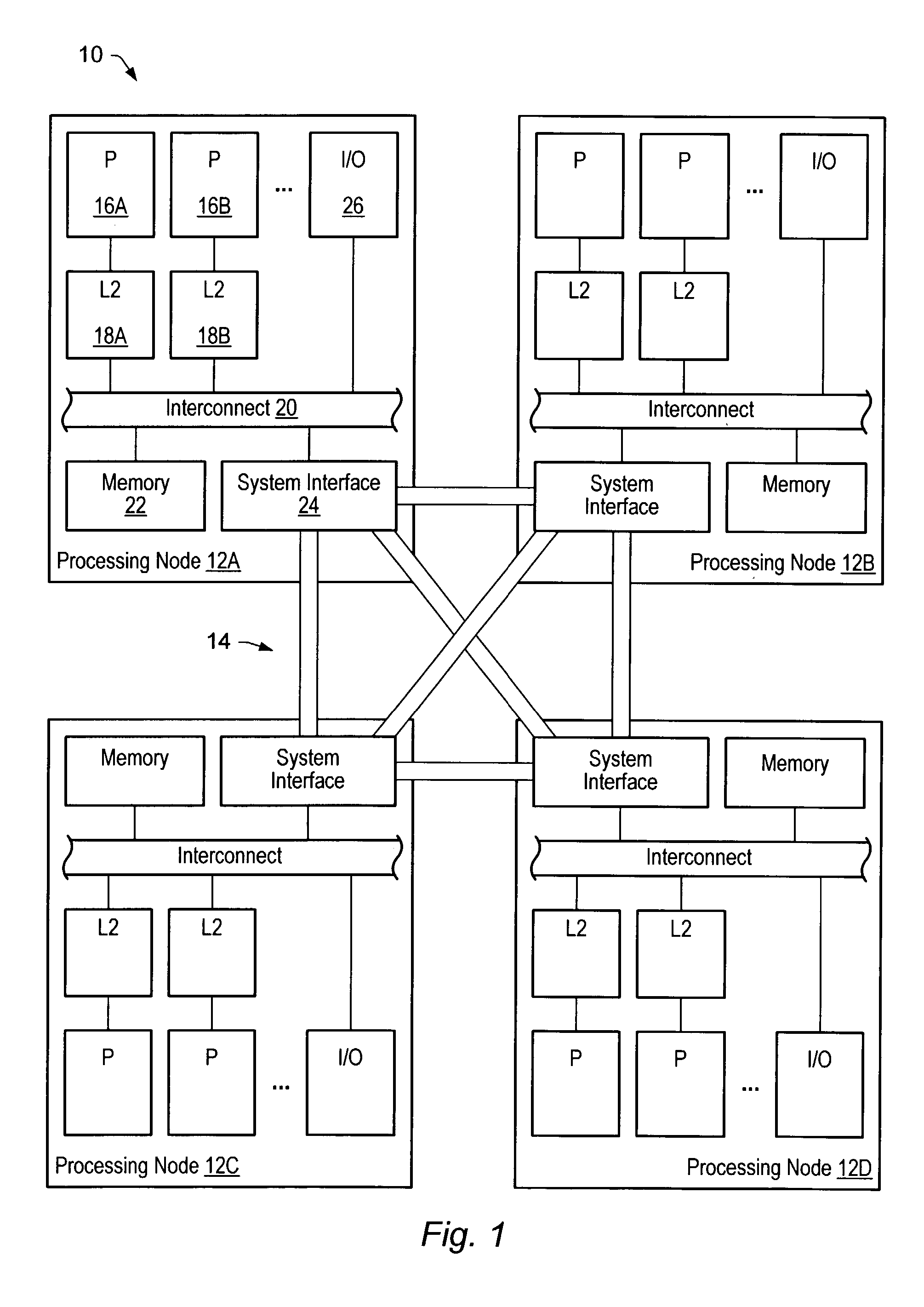
[0022]Turning now to FIG. 1, a block diagram of one embodiment of a multiprocessing computer system 10 is shown. Computer system 10 includes multiple processing nodes 12A-12D interconnected by a point-to-point network 14. Elements referred to herein with a particular reference number followed by a letter will be collectively referred to by the reference number alone. For example, processing nodes 12A-12D will be collectively referred to as processing nodes 12. In the embodiment shown, each processing node 12 includes multiple processors, caches, a memory, and a system interface. For example, processing node 12A is configured with multiple processors including processors 16A-16B. The processors 16 are connected to caches 18, which are further coupled to a node interconnect 20. Additionally, a memory 22 and a system interface 24 are coupled to node interconnect 20. Still further, one or more input / output (I / O) interfaces 26 may be coupled to node interconnect 20. I / O interfaces 26 are...


PUM


Abstract

A method for controlling a software lock acquirable by processors in a plurality of nodes of a multiprocessing system is disclosed. The method comprises a first processor of a first node of the plurality of nodes acquiring the lock, and the first processor selectively releasing the lock in a first state that allows other processors within the first node to acquire the lock but that prevents processors in a remote node of the plurality of nodes from obtaining the lock. In another embodiment, a method comprises a first processor of a first node attempting to acquire the lock, the first processor determining whether another processor within the same node is remotely spinning on the lock, and the first processor remotely spinning on the lock in response to determining that another processor in the same node is not remotely spinning on the software lock.

Description

[0001]This application claims the benefit of U.S. Provisional Application No. 60 / 375,742, entitled “Scalable Hierarchical Spin-Lock”, filed Apr. 26, 2002.BACKGROUND OF THE INVENTION[0002]1. Field of the Invention[0003]This invention relates to the field of multiprocessor computer systems and, more particularly, to mechanisms and methods for optimizing spin-lock operations within multiprocessor computer systems.[0004]2. Description of the Related Art[0005]A popular architecture in commercial multiprocessing computer systems is a distributed shared memory architecture. A distributed shared memory architecture includes multiple nodes within which processors and memory reside. The multiple nodes communicate via a network coupled there between. When considered as a whole, the memory included within the multiple nodes forms the shared memory for the computer system. Typically, directories are used to identify which nodes have cached copies of data corresponding to a particular address. Co...

Claims


Application Information

Patent Timeline
IPC IPC(8): G06F15/16G06F9/00G06F9/46
CPCG06F9/526
Inventor RADOVIC, ZORANHAGERSTEN, ERIK E.
Owner ORACLE INT CORP
Learn More