

Data duplication method in a disaster recovery system
a disaster recovery system and data duplication technology, applied in error detection/correction, redundant hardware error correction, instruments, etc., can solve the problems of large time required for recovering db, inability to ensure the consistency of stored backups at transaction level, and difficulty in backing up data, so as to improve the added value of disaster recovery system, avoid data deficit, and prepare backups easily
- Summary
- Abstract
- Description
- Claims
- Application Information
AI Technical Summary
Benefits of technology
Problems solved by technology
Method used
Image

Examples
second embodiment
[0126]FIG. 6 shows a second embodiment, in which a buffer 370 reading the log 116 is provided in the DB / storage control unit 300 of the secondary site 2 in accordance with the first embodiment, and the other structures are the same as those of the first embodiment mentioned above.
[0127]In the second embodiment, the DB / storage control unit 300 redoes (reproduces) the determined transaction by applying the log while analyzing the transaction.
[0128]In the present second embodiment, the primary site 1 writes the snap shot generating command in the log 106 at an optional time point regardless of the staticization.
[0129]Next, a description will be given of an example of a process executed by the DB / storage control unit 300 of the secondary site 2 with reference to FIG. 7.
[0130]First, in S40, the local mirror set 350 of the secondary storage apparatus 113 in the secondary site 2 is set to a pair state, the primary volume 310 and the secondary volume 320 are synchronized, and the secondary ...
modified embodiment 1
[0144]FIG. 8 shows an example in a case of working the process in the DB / storage control unit 300 in accordance with the second embodiment with the searching and referring operation starting process of the secondary DBMS 111 in the secondary site 2.
[0145]S40 to S52 in FIG. 8 are the same as those of the second embodiment mentioned above, and FIG. 8 is different in that a process (S61) of noticing that the snap shot is generated in the secondary DBMS 111 is added after the process in S50.
[0146]S70 to S73 in FIG. 8 show an example of the searching and referring operation starting process of the secondary DBMS 111.
[0147]S70 executes an initializing process for the secondary DBMS 111 starting the searching and referring operation, and S71 waits until the notice from the DB / storage control unit 300 reaches.
[0148]When the secondary DBMS 111 receives the notice that the generation of the snap shot is finished from the DB / storage control unit 300, the secondary DBMS 111 mounts the secondary...
modified embodiment 2
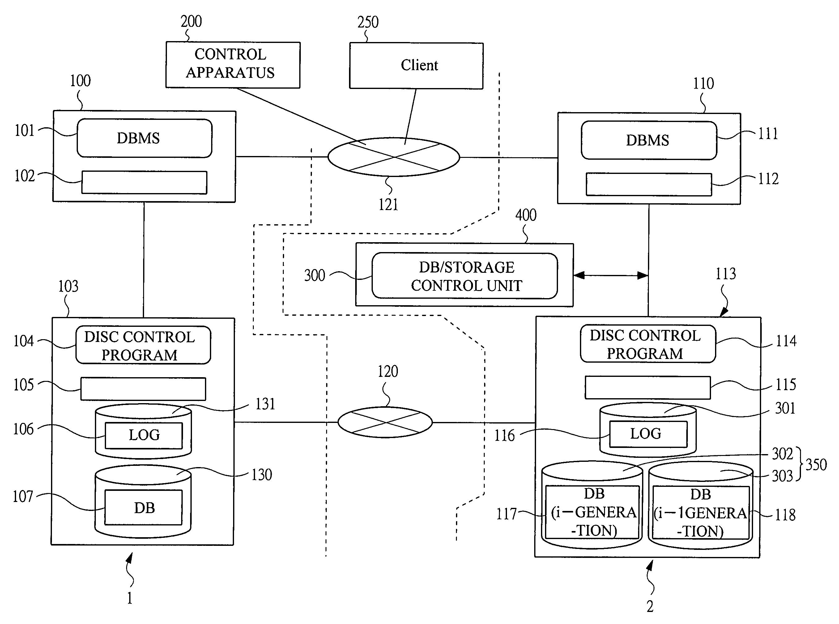
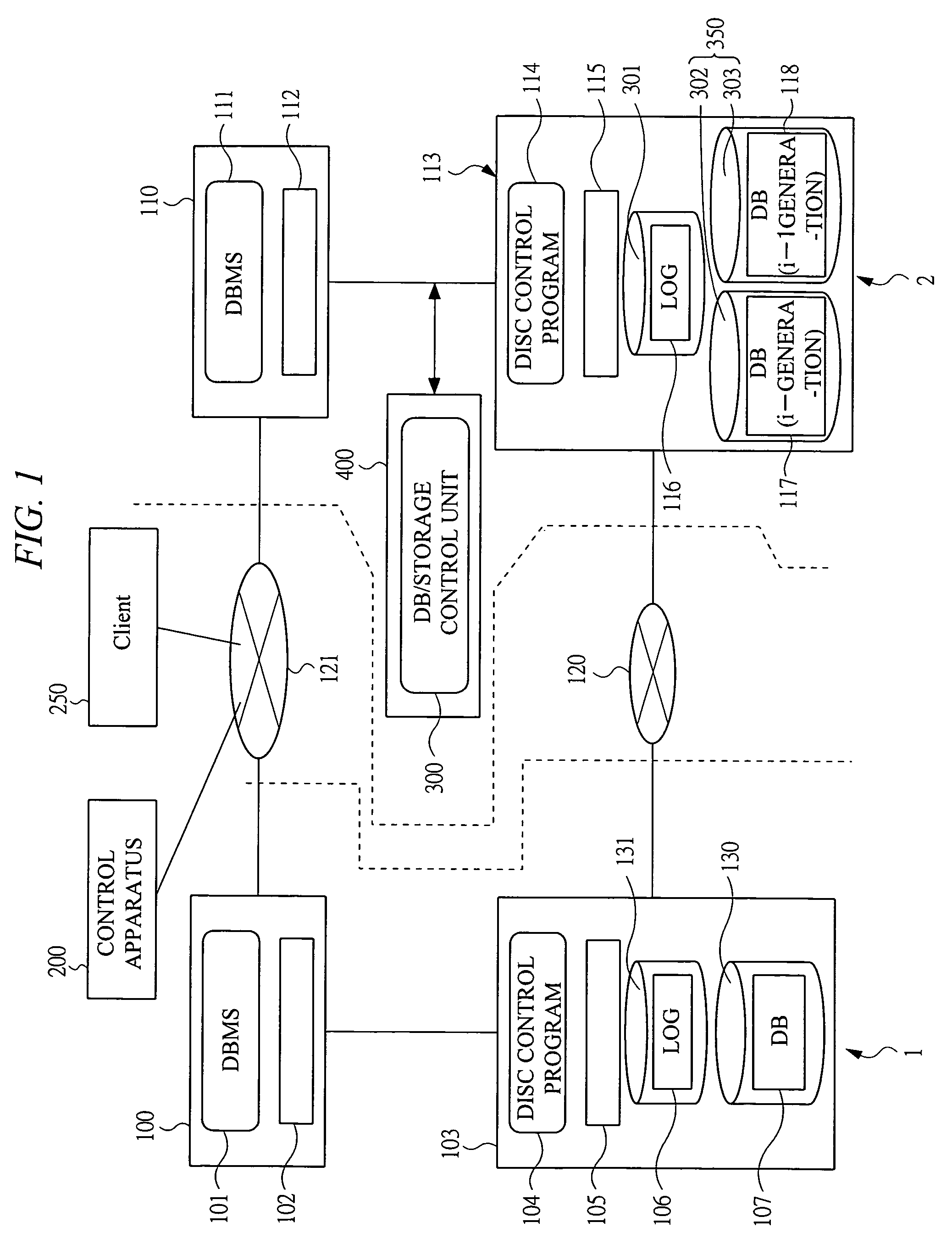
[0151]FIG. 9 shows a structure obtained by replacing the secondary storage apparatus of the secondary site 2 in accordance with the first embodiment mentioned above by NAS 113A, and the other structures are the same as those of the first embodiment mentioned above.
[0152]The NAS 113A is provided with the disc control program 114, the cash 115, the local mirror set constituted by the disc storage units 302 and 303, and the disc storage unit 301, in the same manner as the secondary storage apparatus 113 in accordance with the first embodiment mentioned above, and the DB / storage control unit 300 is executed in addition to the disc control program 114, in a control unit (not shown) of the NAS 113A.
[0153]In this example, the exclusive apparatus 301 for executing the DB / storage control unit 300 shown in the first embodiment mentioned above is not required, and it is possible to lower a cost required for constructing and maintaining the DR system.
PUM
 Abstract
Description
Claims
Application Information