Counterweight based rocket launch platform

a rocket launch platform and counterweight technology, applied in the field of counterweight lifting methods, can solve the problems of the most expensive part the greatest distance of the launch vehicle, and the problem of near-excluding growth

Active Publication Date: 2009-05-12
WATTS KEITH PETER
View PDF4 Cites 7 Cited by
  • Summary
  • Abstract
  • Description
  • Claims
  • Application Information

AI Technical Summary

Problems solved by technology

The disadvantage of these systems is that they launch the greatest distance to space and through the thickest part of the atmosphere.
It is a problem of near exponential growth.
These first stases are the largest and consume the most fuel and are the most expensive part of the launch vehicle.
In addition, most launch facilities are located in coastal regions where they are subjected to severe weather and can be inoperable for periods of time.
From a military perspective they are also vulnerable to attack with little natural protection.

Method used


Image

  • Counterweight based rocket launch platform
  • Counterweight based rocket launch platform
  • Counterweight based rocket launch platform

Examples


Embodiment Construction

[0022]The particular values and configurations discussed in these non-limiting examples can be varied and are cited merely to illustrate embodiments of the present invention and are not intended to limit the scope of the invention.

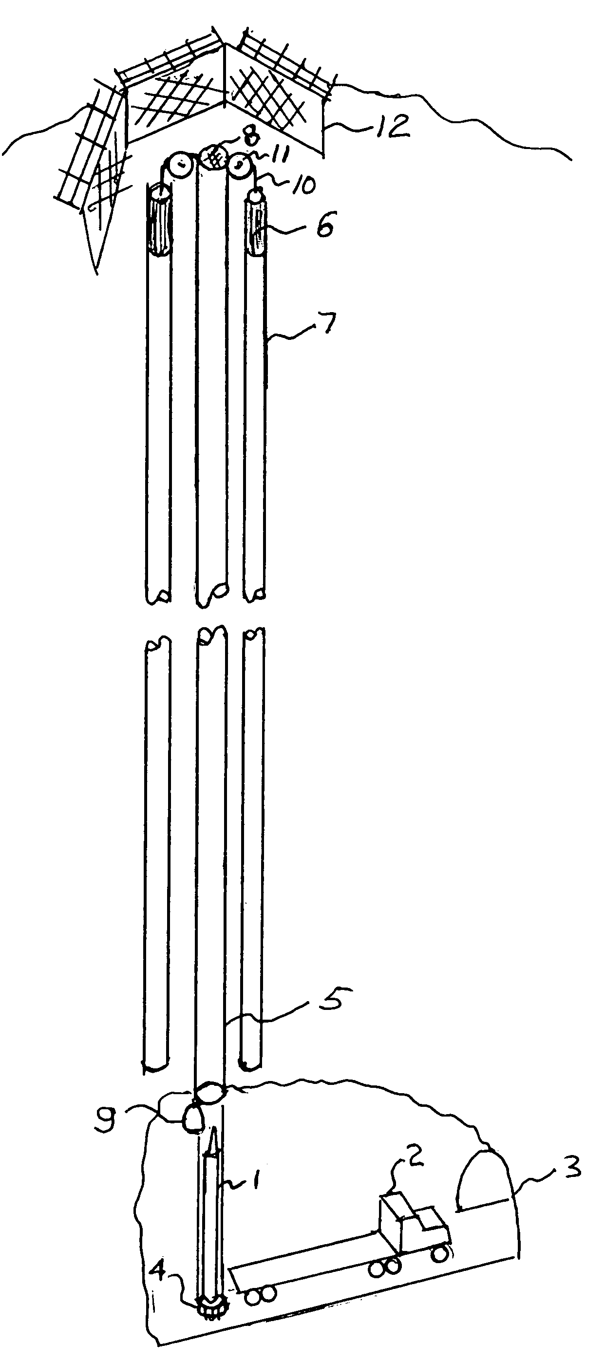
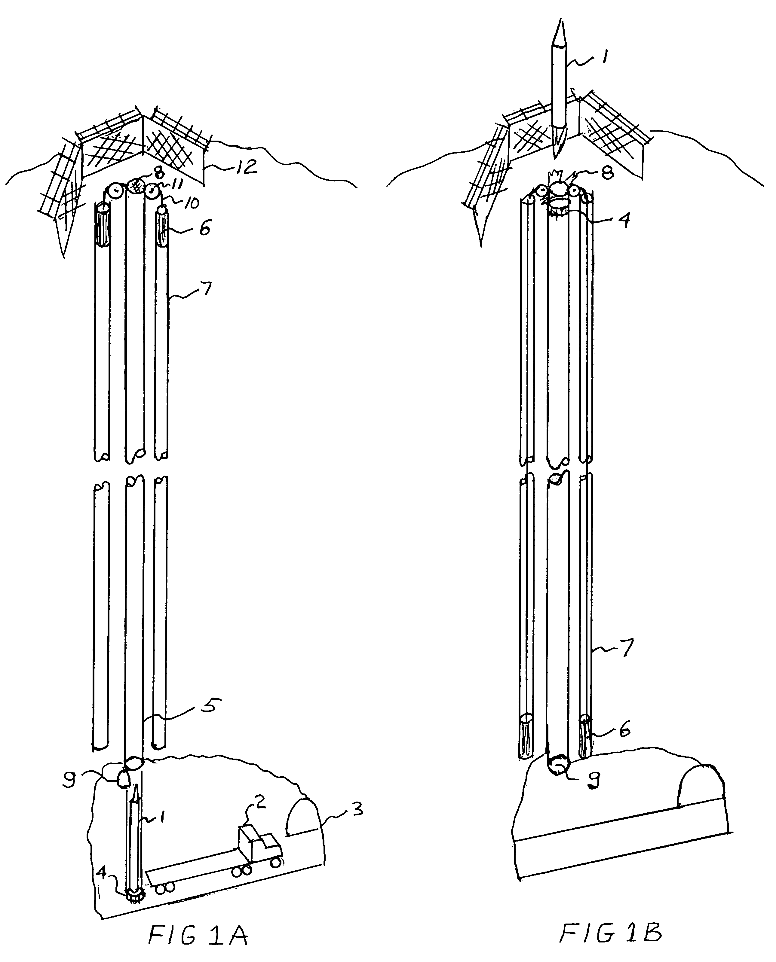
[0023]FIGS. 1a and 1b are environmental isometric views of the mountain launch system. Only two counterweight tubes are shown for clarity. FIG. 1a shows the pre-launch configuration. The rocket 1 is brought in on a truck 2 through an access tunnel 3. The rocket is then placed onto the launch platform 4 below the launch tube 5. The counterweights 6 are shown in their upper position at the top of the counterweight tubes 7. There is a thin membrane 8 stretched across the top of the launch tube and a door 9 at the bottom of the launch tube which when closed will allow the system to be evacuated to minimize aerodynamic drag. The counter weights are attached to the launch platform with high strength wire ropes 10 routed over pulleys 11 located between the launch...


PUM


Abstract

A counterweight based rocket launch platform system and method uses gravity acting upon a counterweight to provide the initial assent for a rocket. This counterweight system is preferably built inside of a mountain so as to use the mountain as the supporting structure. By covering the exit opening with a thin membrane and closing the bottom, the system can have the air evacuated providing a free ascent without a terminal velocity. During the final moments of the ascent or after the rocket leaves the tube, the rocket will ignite carrying the payload into space. The velocity imparted to the rocket from the gravity assist in combination with bypassing the thickest part of the atmosphere will lower the amount of fuel required to lift payloads into space. This will result in increased payloads of existing rockets or the use of smaller and less expensive rockets.

Description

TECHNICAL FIELD[0001]Embodiments are generally related to rocket launch methods, devices and systems. Embodiments are additionally related to counter-weight lifting methods, devices and systems. Embodiments are also related to terrain based rocket launch facilities.BACKGROUND[0002]Most of the launch systems in use today operate from a standstill at or near sea level. The disadvantage of these systems is that they launch the greatest distance to space and through the thickest part of the atmosphere. They must carry enough fuel to not only lift the payload but also to carry fuel to lift the fuel. It is a problem of near exponential growth.[0003]In the case of the space shuttle, half the fuel (1.5 million pounds) is used in the first 8 seconds getting to a height of only 300 ft. Typically, the first stage of a launch system is used to get the rocket and payload from a standstill through the lower atmosphere. These first stases are the largest and consume the most fuel and are the most ...

Claims


Application Information

Patent Timeline
Patent Type & Authority Patents(United States)
IPC IPC(8): B64G1/40
CPCB64G1/002B64G5/00
Inventor WATTS, KEITH PETER
Owner WATTS KEITH PETER
Why Eureka
Try Eureka