Electronic module

a technology of electronic modules and latch mechanisms, applied in the direction of optical elements, coupling device connections, instruments, etc., can solve the problems of large dimensions of latch mechanisms, difficulty in size reduction, and inability to disengage, so as to reduce the space required for latch mechanisms and effectively use packaging spa

Inactive Publication Date: 2009-05-12
HITACHI METALS LTD
View PDF6 Cites 14 Cited by
  • Summary
  • Abstract
  • Description
  • Claims
  • Application Information

AI Technical Summary

Benefits of technology

[0021]According to the present invention, it is possible to reduce space required for a latch mechanism, and effectively use packaging space.

Problems solved by technology

However, the above electronic module 41 bends the arms 44 inwardly in the direction of width to cause the latch members 43 to sink into the module body 42, and therefore requires in the module body 42 movable space with at least the same size as the projection width of the latch members 43, which results in the problem of large dimensions of the latch mechanism, and difficulty in size reduction.
With the above electronic module 41, there is also the problem that the latch members 43 cannot be disengaged from the cage 40 with weak force of pinching the arms 44, and the electronic module 41 cannot therefore be easily and smoothly pulled and removed.

Method used


Image

  • Electronic module
  • Electronic module
  • Electronic module

Examples


Embodiment Construction

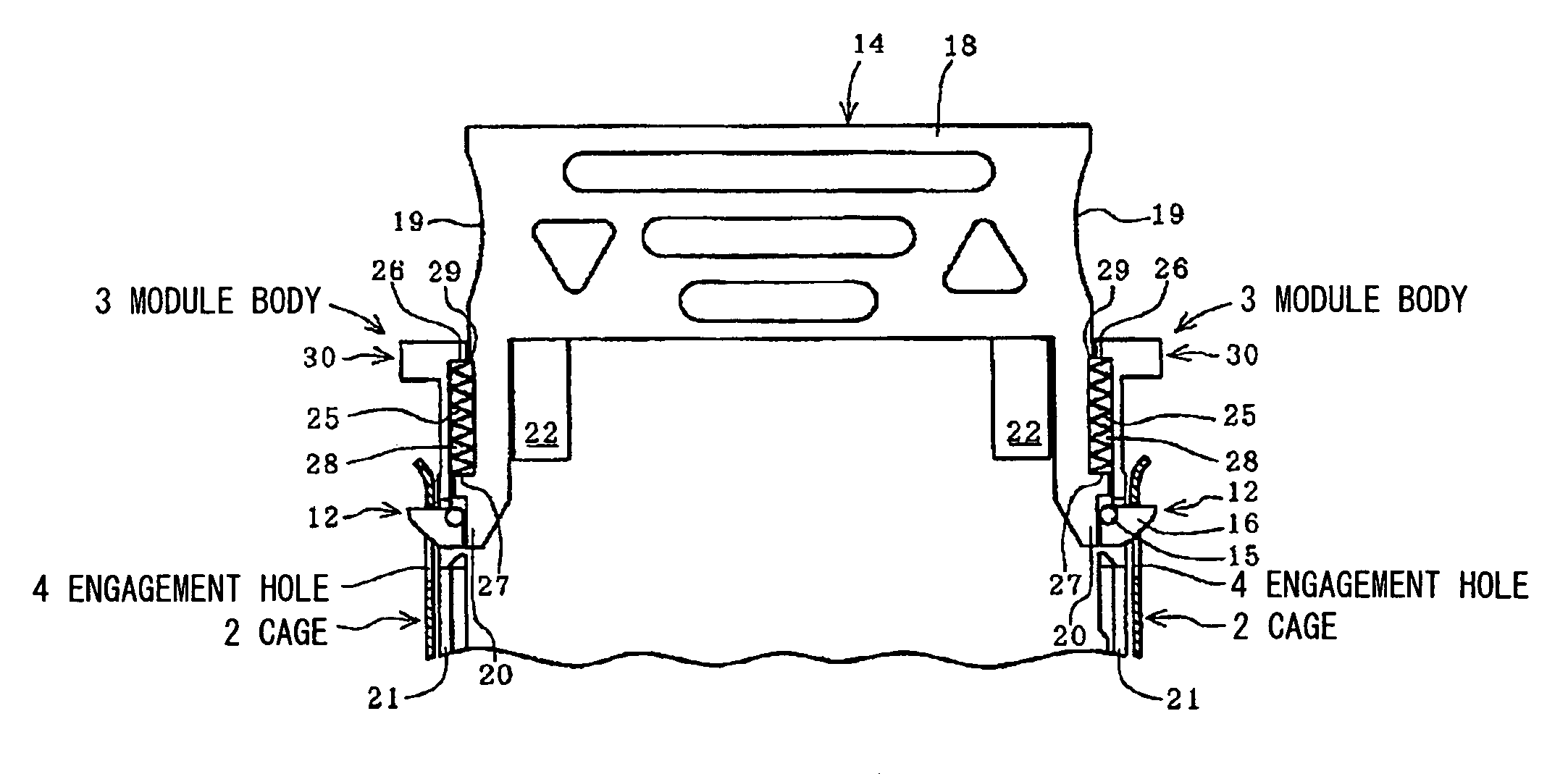
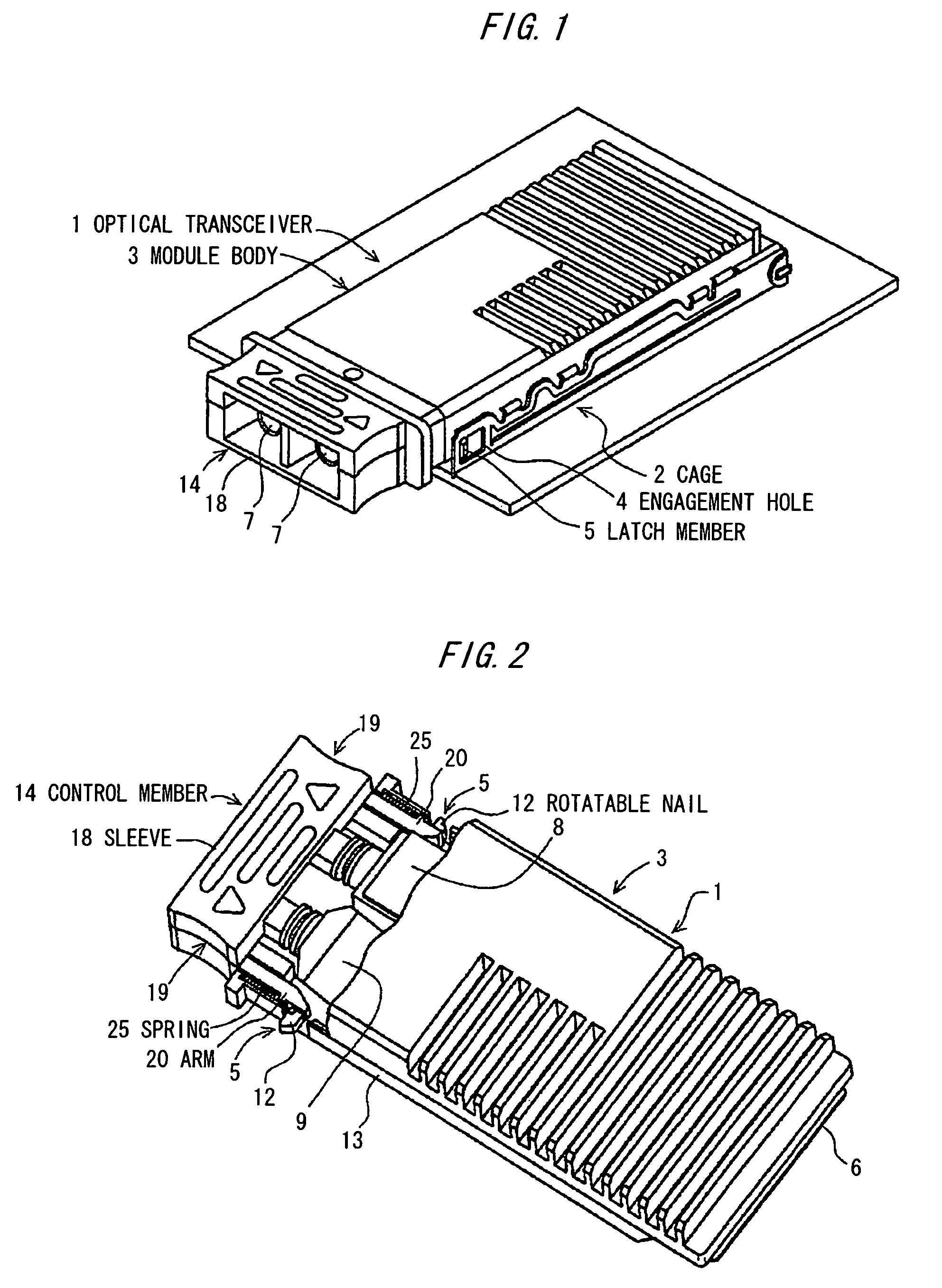
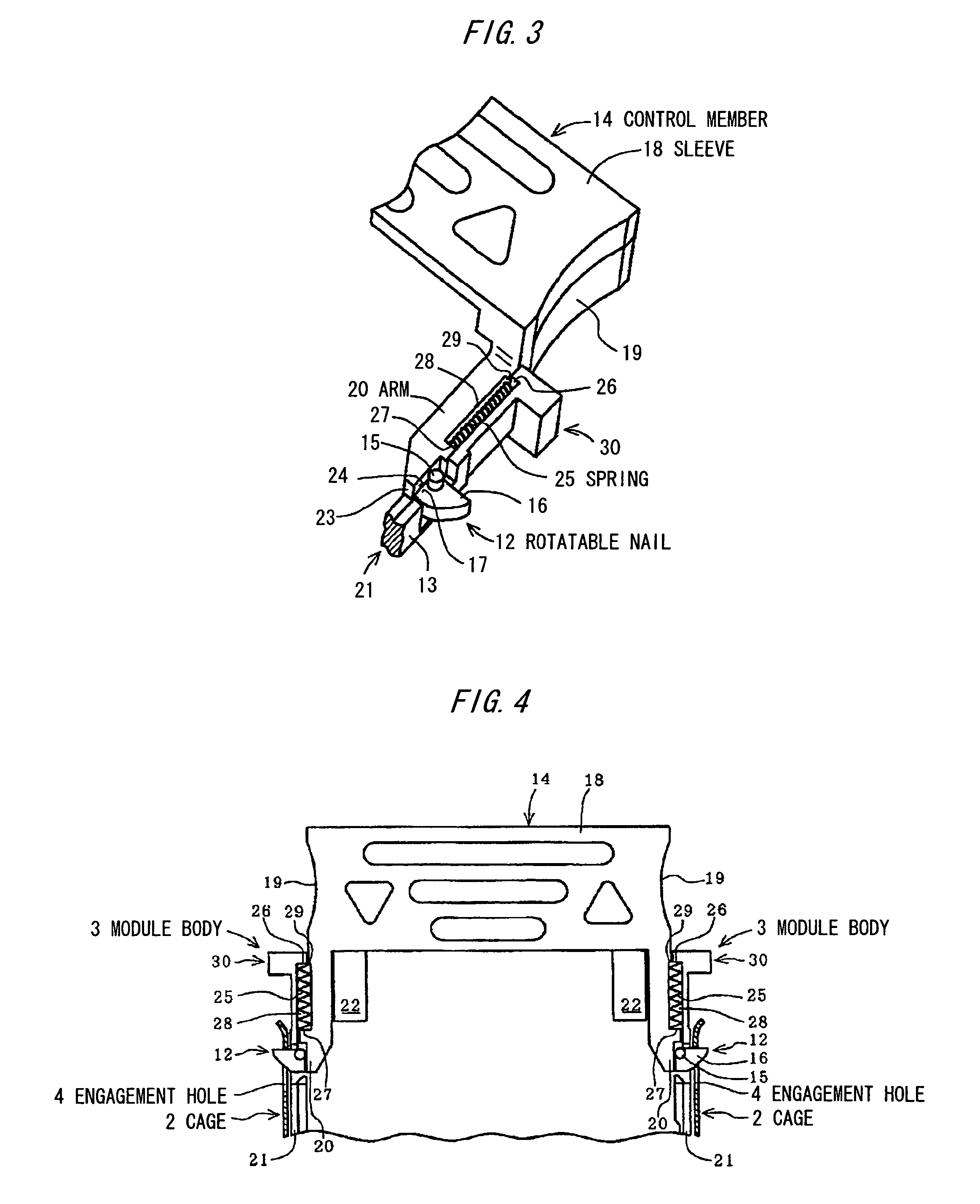
[0039]FIGS. 1 and 2 show an optical transceiver that serves as an electronic module. This optical transceiver 1 includes a module body 3 provided to be removably inserted into a cage 2. The module body 3 includes a latch member 5 which engages an engagement hole 4 formed in the cage 2 during insertion into the cage 2.

[0040]The cage 2 has standard dimensions and shape. It has on both sides the engagement hole 4 for locking the optical transceiver 1, and thereinside a connector (not shown) to be electrically connected to the optical transceiver 1.

[0041]The module body 3 is formed in a long box shape in an insertion direction. It has at an insertion fore-end a card edge 6 connected to the connector inside the cage 2, and at an insertion rear end an optical connector 7 connected to an optical cable (not shown). The module body 3 also has thereinside a small-size transmitter optical sub-assembly (TOSA) 8, a small-size receiver optical sub-assembly (ROSA) 9 and a plurality of circuit subs...


PUM


Abstract

An electronic module is provided with a module body for being removably inserted into a cage; a latch member provided in the module body for engaging an engagement hole formed in the cage during insertion into the cage; a rotatable nail for engaging / disengaging the engagement hole of the cage and being rotatably provided in the module body so as to appear above and sink below a module body surface; and a control member provided in the module body for rotating the rotatable nail.

Description

[0001]The present application is based on Japanese patent application Nos. 2005-150724, the entire contents of which are incorporated herein by reference.BACKGROUND OF THE INVENTION[0002]1. Field of the Invention[0003]The present invention relates to an electronic module with a latch member that engages a cage.[0004]2. Description of the Related Art[0005]As shown in FIG. 16, an electronic module 41 is known, such as an optical transceiver to be removably inserted into a cage 40, in which latch members 43 which engage the cage 40 are respectively provided on both sides of a module body 42, so as to be spring-biased outwardly in the direction of width. Specifically, this electronic module 41 has plate-spring arms 44 on both sides respectively, with which are provided the latch members 43. The arms 44 each are fixed to the module body 42 at an end in an insertion direction, and freely formed at a tip. The tips of the arms 44 are pushed and narrowed to thereby move the latch members 43 ...

Claims


Application Information

Patent Timeline
Patent Type & Authority Patents(United States)
IPC IPC(8): H01R13/64G02B6/36
CPCH05K7/1405
Inventor YU, JUHYUNTAKAHASHI, RYUTASUNAGA, YOSHINORI
Owner HITACHI METALS LTD
Why Eureka
Try Eureka