Eureka AIR delivers breakthrough ideas for toughest innovation challenges, trusted by R&D personnel around the world.

Travel limited linear belt tensioner

Inactive Publication Date: 2009-05-12
BONUTTI 2003 TRUST A THE
View PDF15 Cites 17 Cited by
  • Summary
  • Abstract
  • Description
  • Claims
  • Application Information

AI Technical Summary

Benefits of technology

[0025]The present invention has as an object the provision of a linear accessory power transmission belt drive tensioner, a system of a configuration, an engine utilizing the same, and method for their use, that improves the combination of short-term performance, long-term performance, and optimizes belt selection.

Problems solved by technology

Such worst case conditions can be the result of extremes of temperature, engine operation, or accessory operation.
The limitations of the locked-center approach to belt tensioning are exacerbated in serpentine applications.
However, a tensioner with only these elements may not maintain appropriate tension upon the belt for all operating conditions of the system.
An operating power transmission belt drive system typically oscillates due to the influences of torsional vibration or other angular acceleration of the crankshaft or accessories, the influences of unbalanced conditions, or other influences.
The oscillations lead to vibration of the belt.
This, in turn, leads to vibration of the moveable portions of the tensioner.
The changing tension upon the belt can cause unacceptable performance for the belt drive system.
In one instance, issues of short-term performance, such as where the belt of the belt drive system slips excessively limiting the system's efficiency or power transmission capability, or is excessively noisy due to slippage or otherwise, can arise.
In another instance, the amount of tension necessarily applied to the belt, to have acceptable performance on the short-term, leads to long-term issues such as premature failure of one or more components of the system, including the belt, or one or more accessories.
The other direction tends to wedge the shoe against the race and increase the damping.
The inclusion of hydraulics creates the concern of leaking hydraulic fluid.
The relatively large number of parts adds to cost and complexity of construction.
Further, there is no provision for compensating for the parasitic torque across the carrier that supports the idler pulley, which tends to twist that carrier, other than the effectiveness of the ball and track bearing structure.
This feature substantially increases the demands placed upon accessory belt drives.
The advent of Gen-Star systems causes the designer, of power transmission belt drive systems, to face substantial new challenges, above mere oscillatory loads.
A significant challenge, among these, has been to develop a tensioning system that results in acceptable performance, by an accessory belt drive that includes this new device, which not only offers substantial load and rotational inertia, but also adds large driving torque into the accessory belt drive.
Further, it provides this large driving torque on an intermittent basis.
It has also been discovered that placing specific limits on the travel of the tensioner in the belt loosening direction can positively affect both short-term and long-term performance of such a belt drive system.
However, deleterious side effects caused by such a travel limitation include undesirable belt and other system noise, when the limits are reached.
This tensioner is apparently complex, requires special mounting of the motor / generator having moving parts subject to wear, and is not flexible in its application.
Further, the '208 patent does not disclose the contemplation of adding damping to the movement of either pulley to enhance system performance.
Also, it does not disclose a travel limiting structure that is either resilient, cooperates with a damping mechanism, or suggests an attempt at overcoming the previously described deleterious side effects.

Method used


Image

  • Travel limited linear belt tensioner
  • Travel limited linear belt tensioner
  • Travel limited linear belt tensioner

Examples


Embodiment Construction

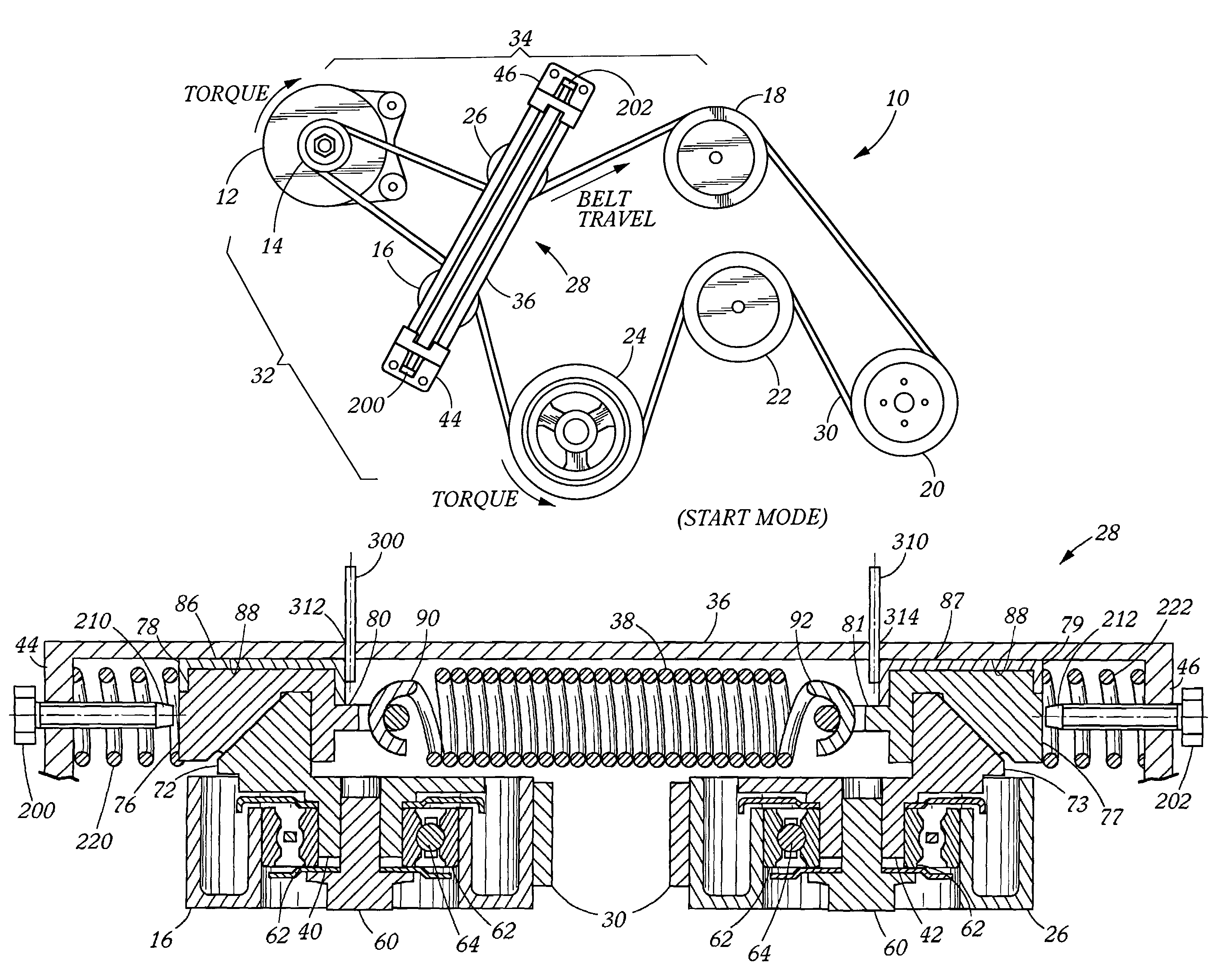
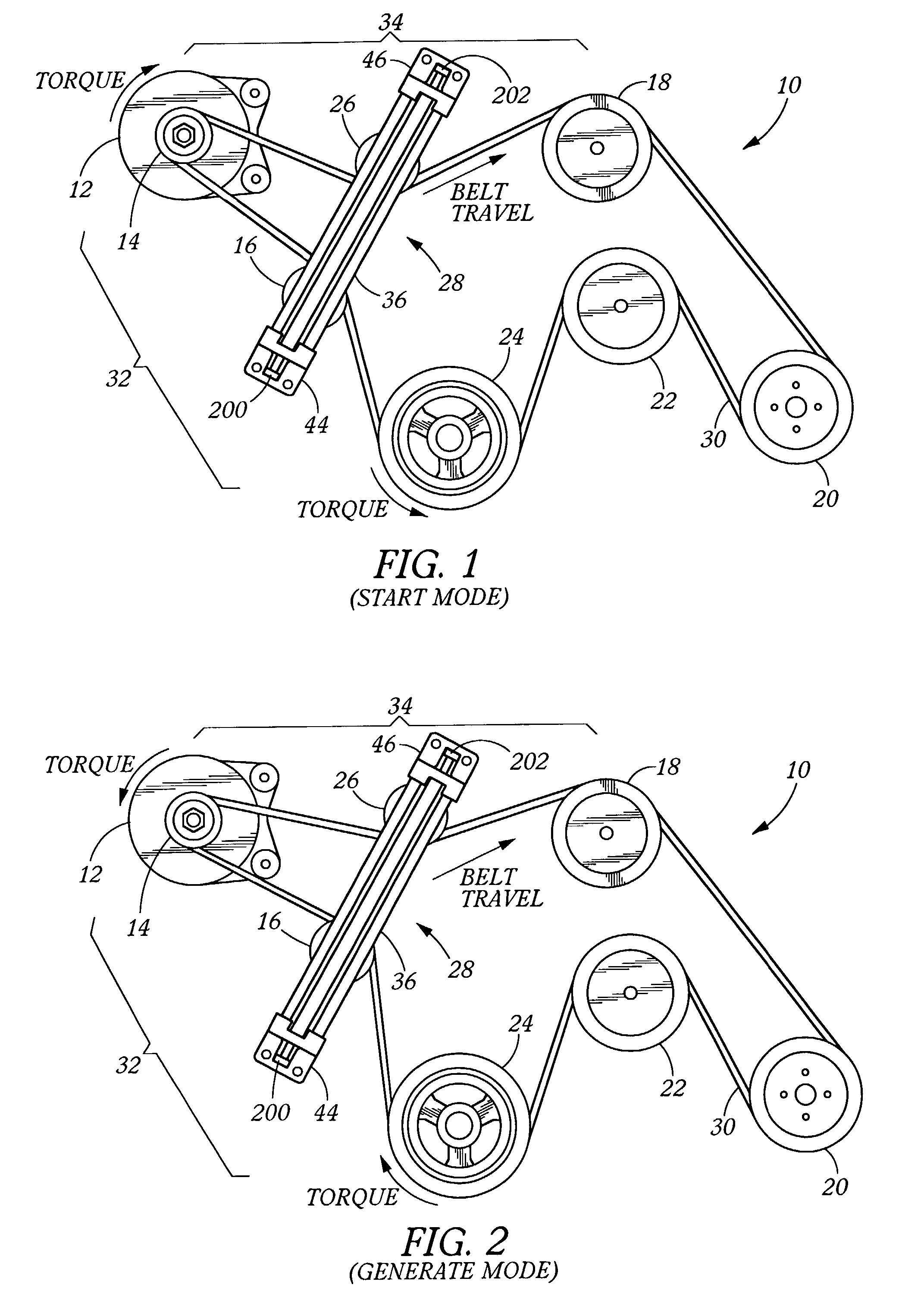
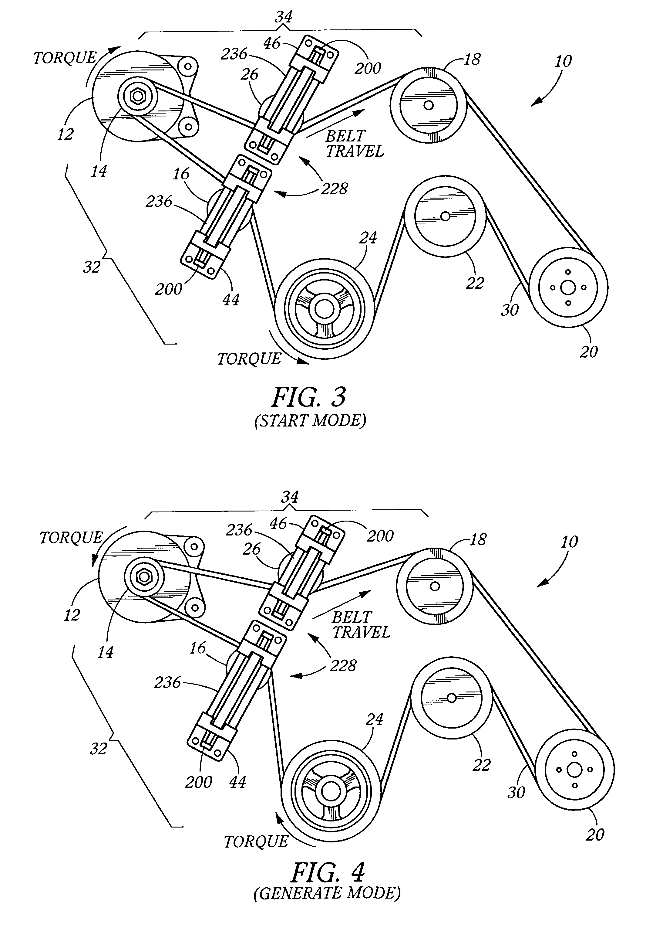
[0052]A preferred embodiment of an accessory belt drive system 10 is depicted in FIGS. 1 and 2. It includes motor / generator 12, motor / generator pulley 14, power steering pump pulley 18, air conditioning compressor pulley 20, water pump pulley 22, crankshaft pulley 24, dual tensioner 28, first tensioner pulley 16, second tensioner pulley 26, and power transmission belt 30.

[0053]While specific accessory pulleys in a specific geometrical arrangement are depicted, it should be recognized that the instant invention applies to various numbers and combinations of accessories and geometrical arrangements, including both serpentine and non-serpentine configurations, depending upon application. While significant advantages can be obtained for a system including motor / generator 12, the accessory could also be an ordinary alternator or other accessory. Commonly, the accessory 14 will be presenting high oscillatory loads to take advantage of the benefits of tensioner 28 of the instant invention....


PUM


Abstract

A belt tensioner for a belt drive system as a belt tensioner, a first belt tensioner pulley, a crankshaft pulley, an accessory pulley, and a power transmission belt trained about the first belt tensioner, crankshaft, and accessory pulleys. The belt tensioner is of the type that includes an attachment point adapted to be affixed to a stationary point relative to a cylinder block of an engine, a track, and a first carrier mounted in sliding relation with the track with two degrees freedom of movement. The first belt tensioner pulley is rotatably mounted upon the first carrier for engaging the power transmission belt. A resilient member biases the first carrier in longitudinal relation to the track. The tensioner further includes a travel limiting mechanism.

Description

CROSS-REFERENCE TO RELATED APPLICATIONS[0001]This application claims priority to U.S. Provisional Patent application Ser. No. 60 / 332,645, filed Nov. 6, 2001 and entitled Travel Limited Linear Belt Tensioner. The subject matter of this application is incorporated herein by this reference.BACKGROUND OF THE INVENTION[0002]1. Field of the Invention[0003]This invention relates generally to a tensioner for tensioning a power transmission belt of a belt drive system. Particularly, it relates to a tensioner having a linear pulley movement. Specifically, this invention relates to a linear movement tensioner whose movement is mechanically damped and travel limited with included applicability to power transmission belt drive systems having a unitary device performing both the engine starting function and the electrical power generation function, such as a motor / generator sometimes referred to as a Gen-Star.[0004]2. Description of the Prior Art[0005]Internal combustion engines, or power plants,...

Claims


Application Information

Patent Timeline
IPC IPC(8): F16H7/08F16H7/12
CPCF16H7/1218F16H2007/0806F16H2007/0808F16H2007/0825F16H2007/084F16H2007/0846F16H2007/0874F16H7/12
Inventor SERKH, ALEXANDER
Owner BONUTTI 2003 TRUST A THE
Why Eureka
Eureka Blog
Learn More