

Tracking solar shelter
a solar energy and solar energy technology, applied in the direction of heat collector mounting/support, pv power plants, light and heating equipment, etc., can solve the problems of dual-axis tracking, inability to link to other devices, and limited space for dual-axis tracking, so as to maximize the amount of solar energy and minimize the need for space
Inactive Publication Date: 2009-05-12
SACRED POWER CORP
View PDF19 Cites 199 Cited by
- Summary
- Abstract
- Description
- Claims
- Application Information
AI Technical Summary
Benefits of technology
[0012]A primary advantage of the present invention is that it minimizes the need for space to situate a solar power array.
[0013]Another advantage of the present invention is that it tracks solar energy so that it maximizes the amount of solar energy that is harnessed.
Problems solved by technology
The dual tracking systems are, consequently, limited to being disposed on one vertical support structure and must utilize complex support systems to confer sufficient structural integrity to avoid being affected by adverse natural or man-made forces.
They cannot be linked to form larger systems.
U.S. Pat. No. 4,995,377 discloses a tracking solar array, but it is dual-axis tracking and cannot be linked to other such devices.
JP2002194912 discloses a solar carport, but it cannot be linked to provide larger area coverage and does not track the sun's movement.
Therefore, solar tracking capacity has not been applied to larger solar array systems.
The prior art does not address the need to maximize the use of space dedicated to larger solar power systems and to simultaneously maximize the amount of solar energy that can be collected.
Method used
View moreImage
Smart ImageViewing Examples

Examples
example
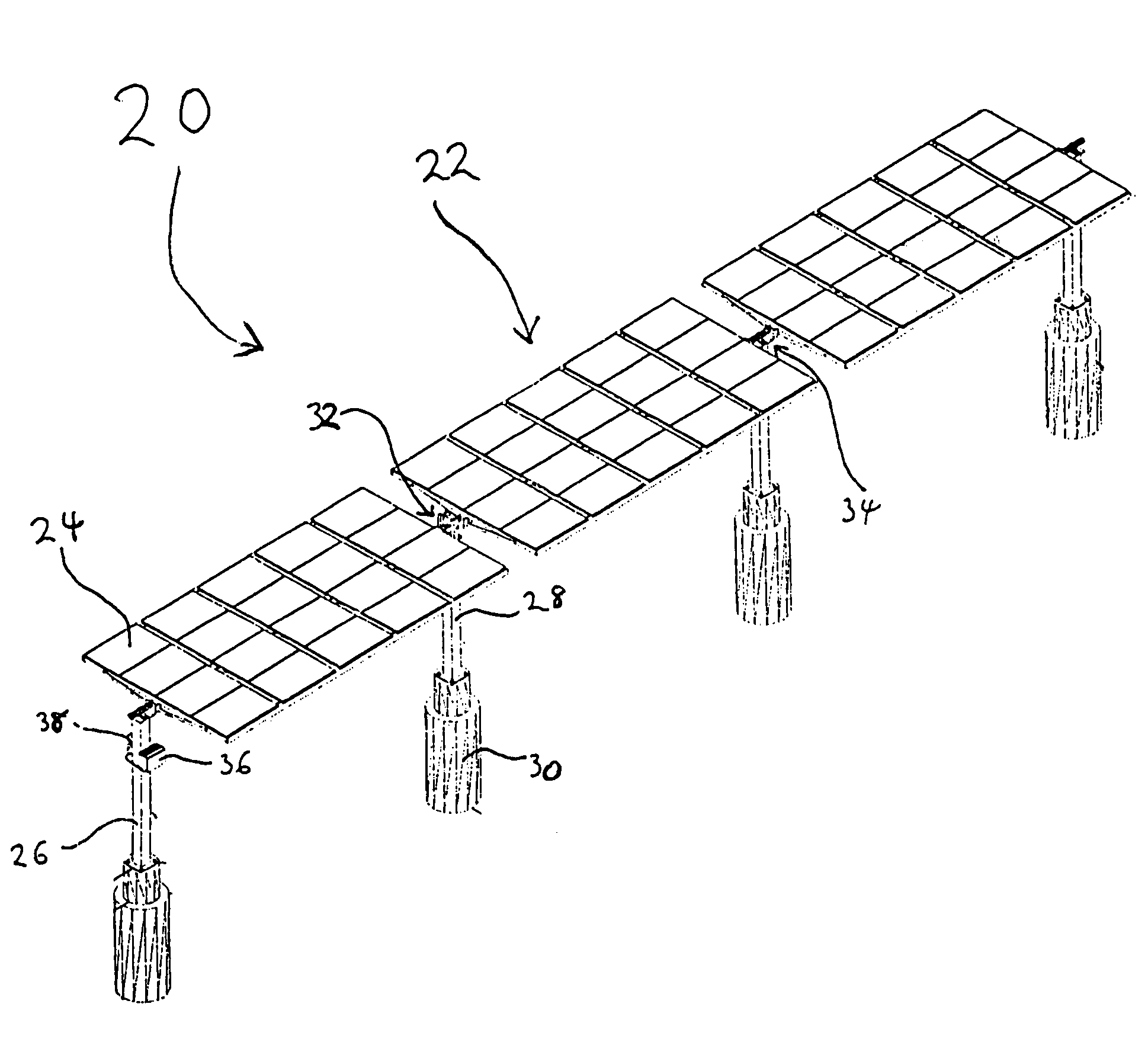
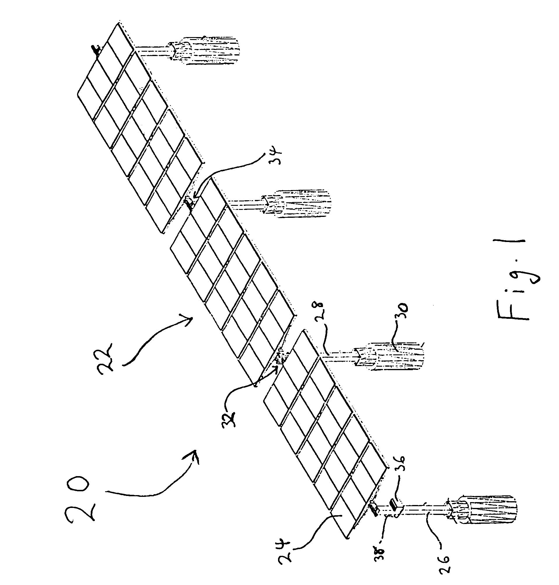
[0053]A solar tracking carport was constructed in accordance with the present invention. There were included twenty Photowatt PW 1250 PV modules per solar array assembly, a 600 Vdc DC disconnect with enclosure per solar array assembly, one 2.5 kW inverter per solar array assembly, a single-axis tracking array apparatus, an AC service panel with enclosure, an AC / Utility main disconnect, 125 watt photovoltaic modules, and disconnects, safety switches and combiner boxes for each section.
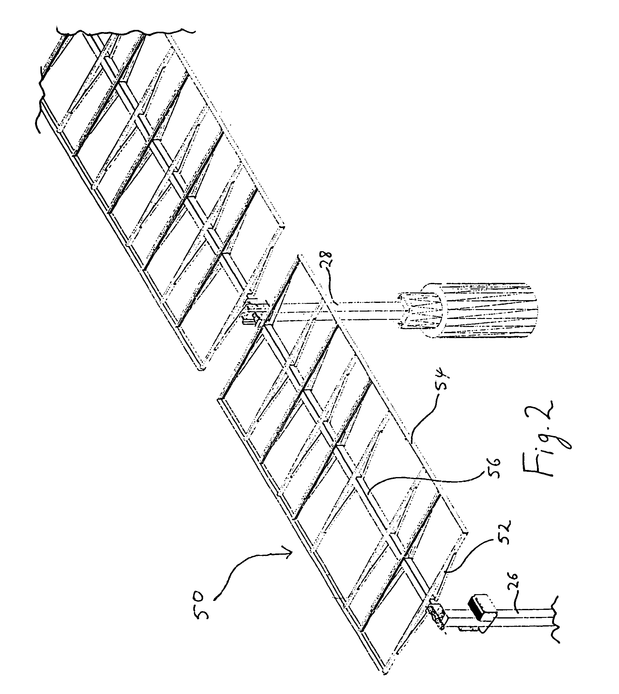
[0054]Each solar array assembly measured approximately 24 feet in length, approximately 12 feet in width, and the bottom edge of each array rose approximately 8 feet, 6 inches in height off the ground.
Login to View More PUM
 Abstract
The present invention comprises a tracking solar power array that provides shelter to items disposed beneath the solar power array, particularly to vehicles.
Description
CROSS-REFERENCE TO RELATED APPLICATIONS[0001]This application claims the benefit of the filing of U.S. Provisional Patent Application Ser. No. 60 / 452,828, entitled “Tracking Solar Array”, filed on Mar. 7, 2003, and the specification thereof is incorporated herein by reference.BACKGROUND OF THE INVENTION[0002]1. Field of the Invention (Technical Field)[0003]The present invention relates to a solar tracking, solar power generating shelter, particularly useful for vehicles.[0004]2. Description of Related Art[0005]Note that the following discussion refers to a number of publications by author(s) and year of publication, and that due to recent publication dates certain publications are not to be considered as prior art vis-a-vis the present invention. Discussion of such publications herein is given for more complete background and is not to be construed as an admission that such publications are prior art for patentability determination purposes.[0006]Methods and devices for generating e...
Claims
Login to View More Application Information
Patent Timeline
 IPC IPC(8): H01L31/00
CPCF24J2/045F24J2/541H02S20/00F24J2/523F24J2002/5482Y02E10/44Y02E10/47Y02E10/50Y02B10/20H02S20/32H02S20/10F24S20/67F24S30/425F24S25/10F24S2030/15
InventorMELTON, DAVID S.ARMIJO-CASTER, ODES
OwnerSACRED POWER CORP