
Composite insulator for fuse cutout

a composite insulator and fuse technology, applied in the field of composite insulators, can solve the problems of heavy and bulky ceramic insulators, and power loss of a section of the grid

Inactive Publication Date: 2009-05-12
MAC LEAN FOGG CO
View PDF26 Cites 13 Cited by
  • Summary
  • Abstract
  • Description
  • Claims
  • Application Information

AI Technical Summary

Benefits of technology

The solution provides a lightweight, easy-to-manufacture insulator that reduces creep distance, prevents flashover, and withstands tension forces, improving the handling and shipping of electrical cutouts while maintaining strength and preventing damage from fuse activation.

Problems solved by technology

If there is a surge in the electrical current on the line, for example, a fuse on the cutout is blown, thereby cutting off power to a section of the grid.
As a result, a section of the grid loses power.
The ceramic insulators, however, are heavy and bulky; they require specialized assembly fixtures or processes and are awkward and difficult to handle and ship.
The ceramic insulators are also brittle and easily chipped or broken.
Problems have arisen with electrical cutouts.
One such problem occurs when electricity flashes directly from a conducting surface to a grounded surface while the fuse assembly is in the open or closed position.
Another problem with conventional cutouts occurs when the electrical current travels or “creeps” along the surface of the insulator, bypassing the fuse assembly.
Creep” results when the insulator has an inadequate surface distance.
Cutouts with plastic or polymeric insulators have been designed; however, such insulators are of complicated design and labor-intensive manufacture.
Other insulators used in cutouts use “fins” or “sheds” which require additional time and labor for assembly.

Method used


Image

  • Composite insulator for fuse cutout
  • Composite insulator for fuse cutout
  • Composite insulator for fuse cutout

Examples


Embodiment Construction

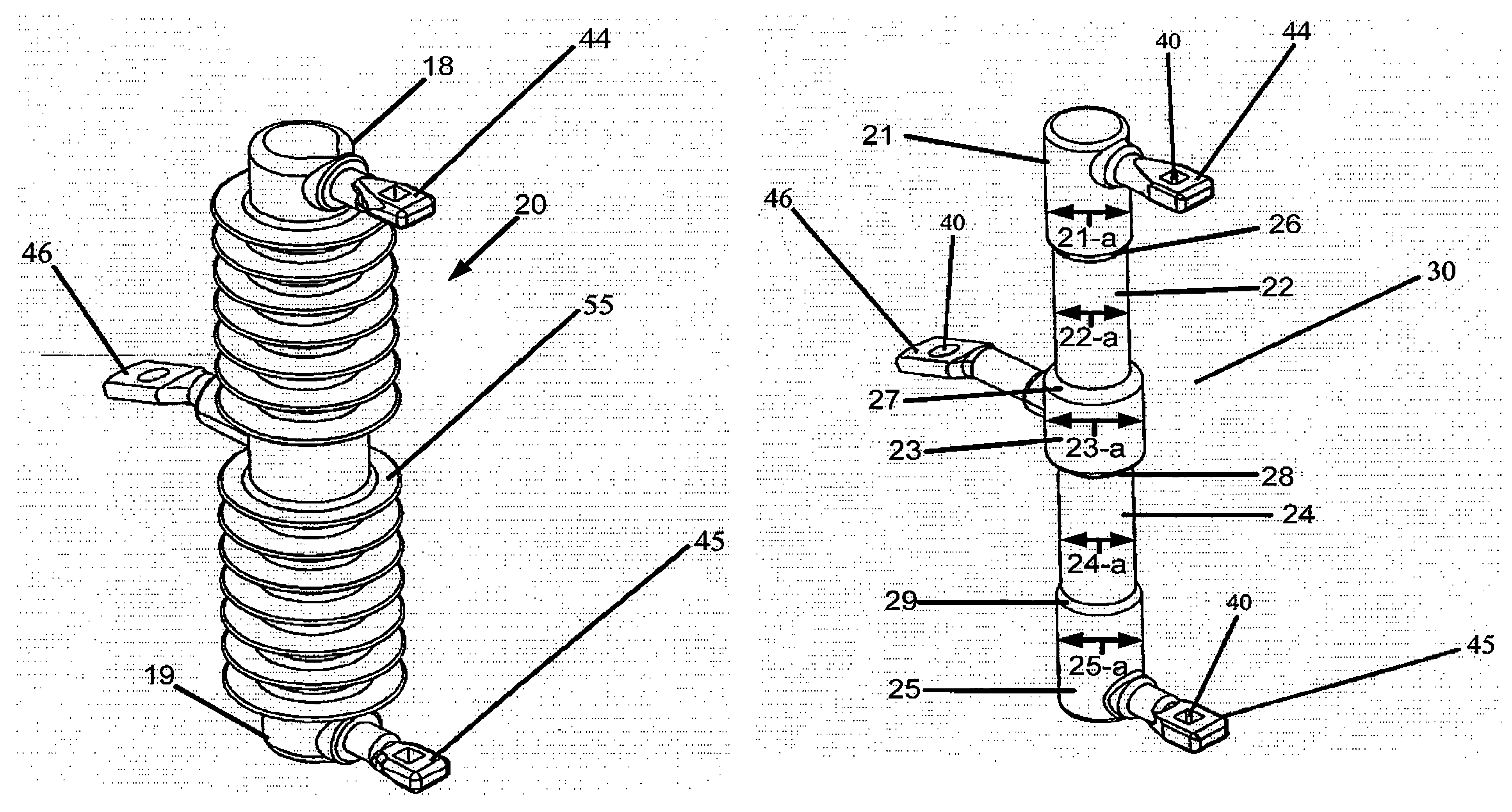
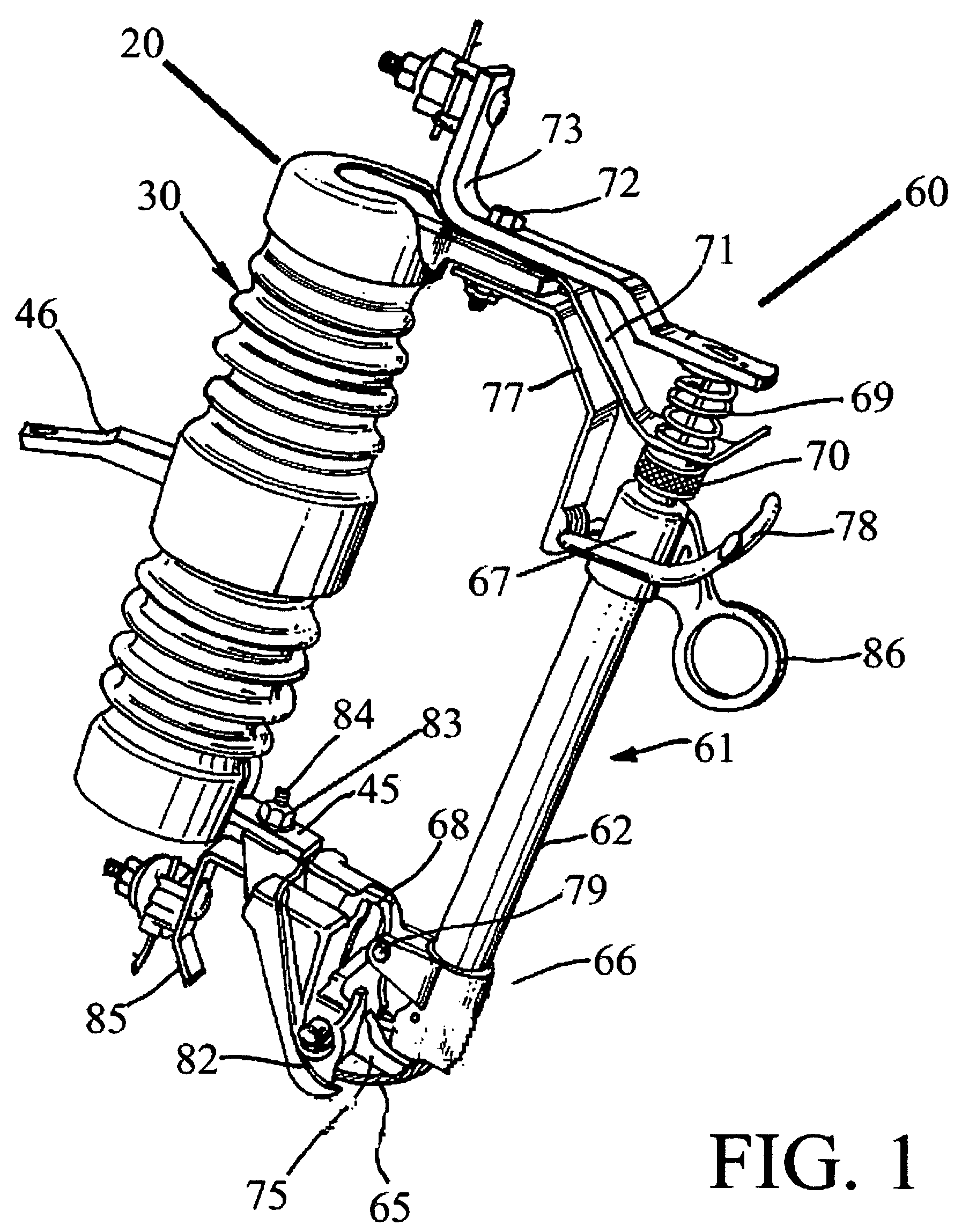
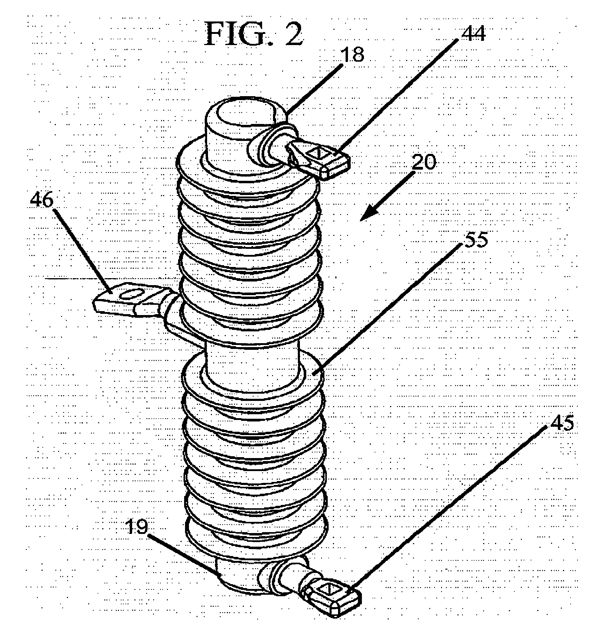
[0023]Turning now to the drawings, FIGS. 1, 2, 3, and 4 show an electrical fuse cutout constituting a preferred embodiment of the present invention, and comprising a fuse assembly 60 and an insulator 20 having a body 30 with connectors 44, 45, 46 and a housing 50.

[0024]The preferred embodiment of the present invention is provided with end connectors 44, 45 and a support connector 46. As shown in FIG. 2, the connectors 44, 45 are located at opposite ends 18, 19 of the insulator 20. According to one aspect of the present invention, the support connector 46 attaches the body 30 to a utility structure, such as a utility pole or, for example, a cross-arm. According to another aspect of the present invention, an end connector 44, 45 couples the body 30 to a conductor. According to yet another aspect of the present invention, an end connector 44, 45 couples the body 30 to a fuse assembly 60.

[0025]FIG. 5 depicts end connectors 44, 45 made in the shape of an “L,” and, as depicted in FIG. 6, ...


PUM


Abstract

The present invention relates to an electrical fuse cutout comprising: (i) an insulator having a composite body and at least two connectors, wherein a first connector couples the composite body to a fuse assembly and a second connector couples the body to a utility structure; (ii) a housing containing the composite body; and (iii) a fuse assembly.

Description

[0001]This application is a continuation of application Ser. No. 10 / 173,386, filed Jun. 16, 2002 now U.S. Pat. No. 6,952,154. The disclosure of application Ser. No. 10 / 173,386 is hereby incorporated herein by reference.FIELD OF THE INVENTION[0002]This invention relates to fuse cutouts for electrical power distribution systems, and particularly to composite insulators used in fuse cutout devices.BACKGROUND OF THE INVENTION[0003]An electrical cutout is a device used to protect an electrical power distribution grid. If there is a surge in the electrical current on the line, for example, a fuse on the cutout is blown, thereby cutting off power to a section of the grid. As a result, a section of the grid loses power. Though a section of the grid experiences power loss, the entire grid is protected from the surge and remains operational.[0004]Electrical cutouts contain three parts: a fuse, an insulator, and a fuse link. When a fuse is blown, physical force is exerted on the insulator. Con...

Claims


Application Information

Patent Timeline
Patent Type & Authority Patents(United States)
IPC IPC(8): H01H85/17H01H85/042H01H31/02H01H31/12
CPCH01H31/127H01H31/023
Inventor ALMGREN, VICTORHENRICKS, SCOTTSCHOMER, MICHAEL J.
Owner MAC LEAN FOGG CO
Learn More