Composite magazine for chambering ammunition in a firearm

a technology for chambering ammunition and firearms, applied in the field of ammunition chambering magazines in firearms, can solve the problems of unsatisfactory need for such magazines, interrupting and slowing the loading process of rounds, and binding of the magazine follower, so as to reduce the jamming, minimize the jamming of the follower, and uniform flow

Inactive Publication Date: 2009-05-19
UNITED STATES OF AMERICA THE AS REPRESENTED BY THE SEC OF THE ARMY
View PDF22 Cites 69 Cited by
  • Summary
  • Abstract
  • Description
  • Claims
  • Application Information

AI Technical Summary

Benefits of technology

[0008]The magazine profile creates a uniform flow for minimizing the jamming of the follower. The follower comprises follower legs and a spring retainer that retains the spring in position. The external profile of the external is such that it travels smoothly upward and downward within the magazine, while loading and dispensing cartridges, tracking the interior of the magazine as the follower is pushed upward by the spring. By mirroring the interior profile of the magazine, the follower has a motion that follows a well-defined path within the magazine.
[0009]The magazine and follower reduce jamming and high friction points throughout the cycle of loading and dispensing rounds of ammunition. In conventional magazine followers, high friction points cause stress or wear on the magazine follower, further causing the magazine follower to jam or otherwise malfunction.
[0010]One object of the present invention is to reduce the stoppage, jamming, and malfunction, in order to improve the long-term durability and reliability of magazines, such as the 30 round magazine.

Problems solved by technology

A conventional 30 round magazine comprises a magazine follower that has a tendency to jam and not properly feed the round into the automatic or semi-automatic firearm.
As rounds are loaded into the magazine, an off-center pressure on the magazine follower can cause the magazine follower to bind, interrupting and slowing the process of loading rounds in the magazine.
The need for such a magazine has heretofore remained unsatisfied.

Method used


Image

  • Composite magazine for chambering ammunition in a firearm
  • Composite magazine for chambering ammunition in a firearm
  • Composite magazine for chambering ammunition in a firearm

Examples


Embodiment Construction

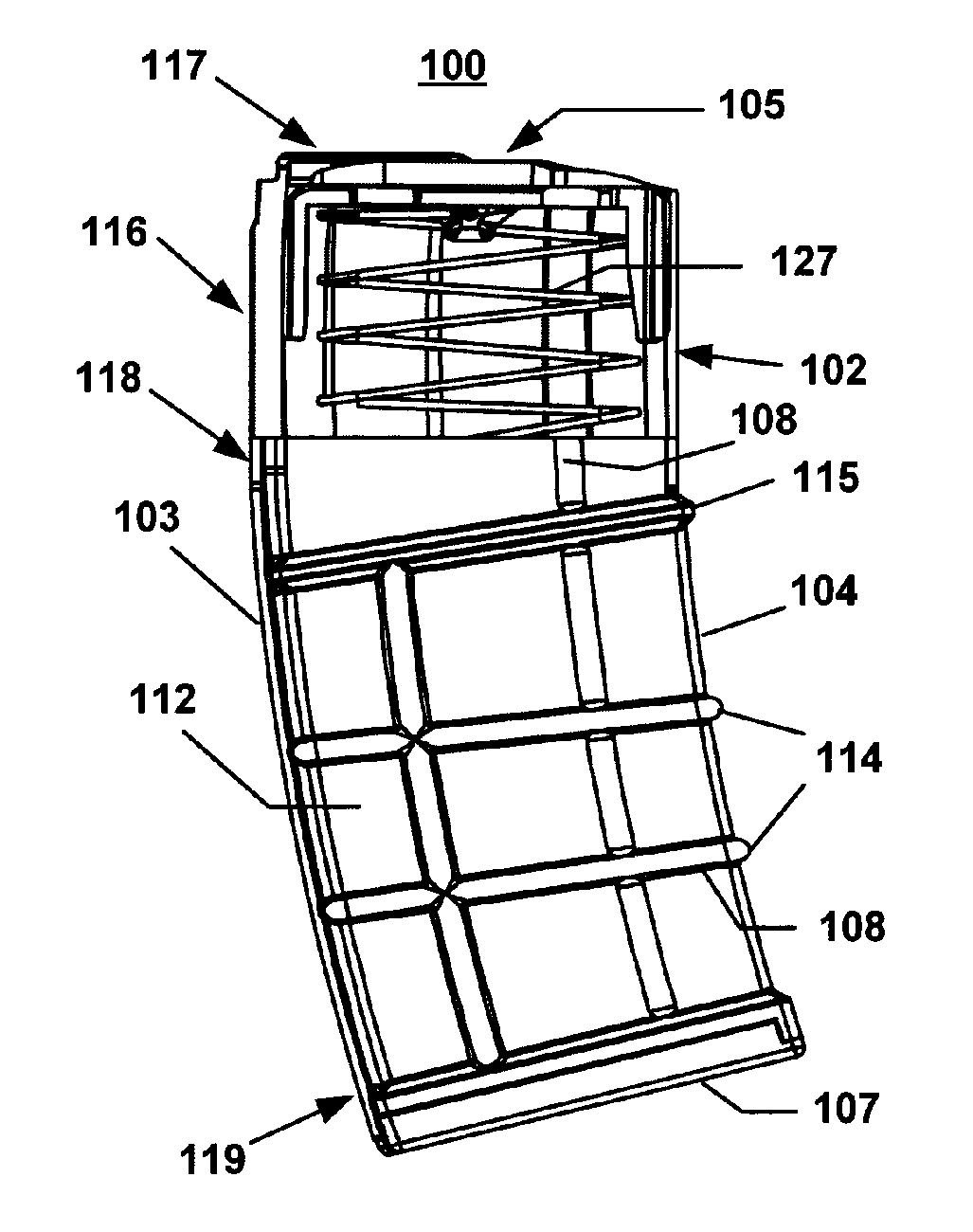
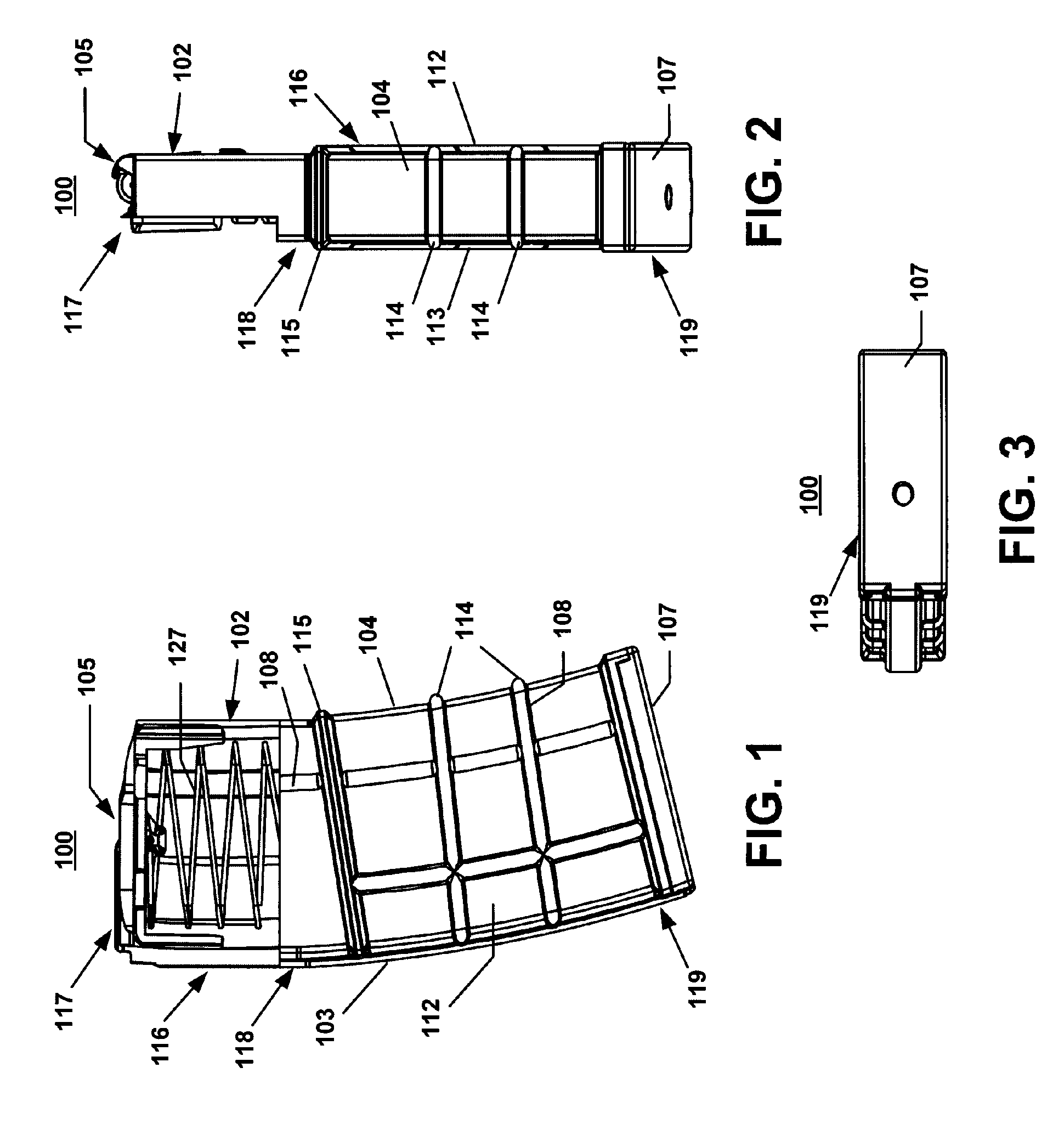
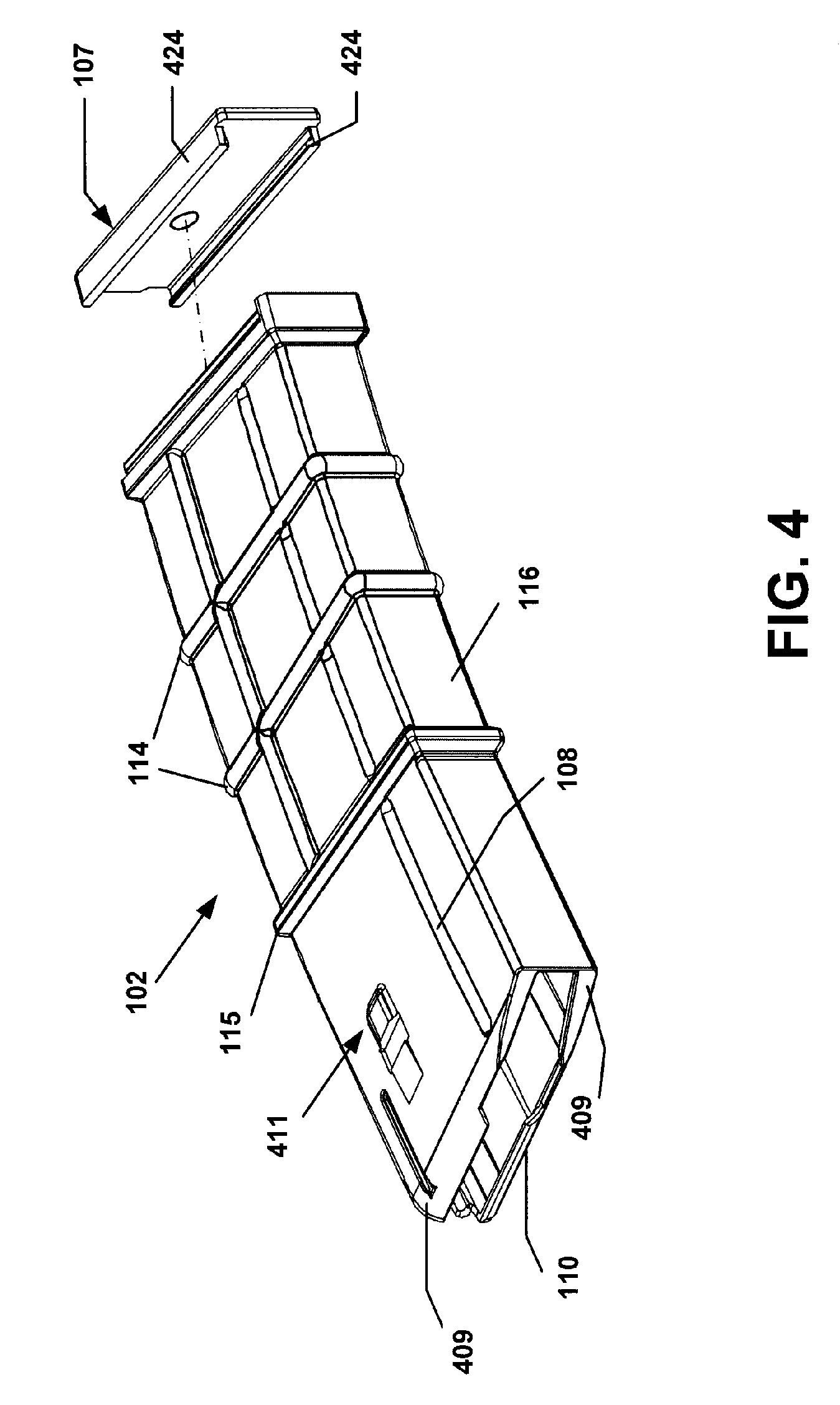
[0023]FIGS. 1, 2, and 3 illustrate an exemplary magazine 100 that generally comprises a housing 102, a follower 105, an elastic element such as a spring 127, a spring hold 106 (illustrated in FIGS. 9, and 11) that is disposed inside the housing 102, and a cap 107. FIG. 1 illustrates the disposition of the spring 127 inside the housing 102. The spring 127 is disposed between the follower 105 and the spring hold 106 adjacent to the cap 107.

[0024]The housing 102 comprises a top end 117, a bottom end 118, and a housing body 119. The housing 102 functions as an external shell of the magazine 100 to accommodate the various components of the magazine 100. In the exemplary magazine 100 shown in FIG. 1, and in particular the 30 round magazine, the housing 102 comprises a curvilinear profile with generally curved surfaces and a substantially rectangular cross section.

[0025]The housing 102 comprises a front wall 112 and a rear wall 113 that are substantially planar and parallel, and two sidewa...


PUM


Abstract

An improved magazine for use in existing firearms comprises a housing, a follower, a spring, a spring hold and a cap. The housing comprises protruded surfaces for structural strength and a projection that acts as a stop member to define the maximum insertion of the magazine into the firearm magazine well. The follower comprises two follower legs and a spring retainer, and travels up and down the housing. The perimeters of the follower and follower legs mirror the internal profile of the magazine housing for a well-defined travel path within the magazine housing. The spring hold comprises a spring retainer and a round protrusion that locks it into the cap via a circular cut. The cap comprises flanges that slide into the slots against the end stop at the bottom of the housing.

Description

FEDERAL INTEREST STATEMENT[0001]The inventions described herein may be manufactured, used and licensed by or for the U.S. Government for U.S. Government purposes.FIELD OF INVENTION[0002]The present invention generally relates to a firearm. More specifically, the present invention relates to a magazine for chambering ammunition in the firearm. In particular, the present invention pertains to a magazine constructed by an injection molding process of a composite material, and a follower formed in the magazine to create an even force distribution on the ammunition within the magazine chamber to minimize jamming.BACKGROUND OF THE INVENTION[0003]Automatic and semi-automatic firearms typically comprise a magazine in which one or more rounds of ammunition are placed. The magazine comprises a magazine follower that pushes the topmost round into position for chambering in the automatic or semi-automatic firearm. For example, a M16 Rifle or M4 Carbine comprises a 30 round magazine. The first r...

Claims


Application Information

Patent Timeline
Patent Type & Authority Patents(United States)
IPC IPC(8): F41A9/65
CPCF41A9/65
Inventor ALZAMORA, RONNYHEINSOHN, JOHNFOLTZ, ADAM
Owner UNITED STATES OF AMERICA THE AS REPRESENTED BY THE SEC OF THE ARMY
Why Eureka
Try Eureka