RFID tag that provides a flat print area and a pinch roller that enables the same

a technology of rfid tags and pinch rollers, applied in the direction of digital output to print units, instruments, digital computer details, etc., can solve the problems of reducing the life of the print head, printing distortion, and less than optimal printing, and achieve the effect of reliable printing and efficient printing

Inactive Publication Date: 2009-08-11
AVERY DENNISON CORP
View PDF52 Cites 2 Cited by
  • Summary
  • Abstract
  • Description
  • Claims
  • Application Information

AI Technical Summary

Benefits of technology

[0005]In accordance with exemplary embodiments of the present invention, radio-frequency identification (RFID) tags enable efficient, reliable printing by providing tags that are effectively flat along their transverse axis as they pass below the print head during the printing process.
[0007]According to another aspect, the layer of adhesive includes a blank that is substantially free of adhesive at the location of the RFID device. The blank essentially provides a recess that effectively accommodates the thickness of the RFID device, thereby resulting in a tag that has a substantially uniform thickness. Accordingly, when passing through a printer, the printable surface is maintained substantially flat or linear at the print head of the printer, thereby minimizing jamming and enhancing printability.
[0008]According to still another aspect, a pinch roller for a printer also accommodates any unevenness in the print surface of the RFID tag when passing through a printer. The pinch roller includes a body that is rotatable about a transverse axis and a deformable section disposed along a length of the body. The deformable section deforms to a greater degree than the rest of the body in a normal direction that is orthogonal to the transverse axis. Accordingly, when an RFID tag with an uneven thickness passes through the printer, the deformable section of the pinch roller accommodates the uneveness by compressing or deflecting in the normal direction.

Problems solved by technology

However, because of the uneven thickness, when passing through a printer during a printing process, the RFID tag has a tendency to jam in the printer or to otherwise present an undesirable printing surface for the print head of the printer, thereby resulting in print distortion and less than optimal printing.
In addition, compressing the RFID tag between the pinch roller and the print head may damage the RFID device and associated inlayed structure or may damage the print head itself, thereby decreasing the life of the print head.

Method used


Image

  • RFID tag that provides a flat print area and a pinch roller that enables the same
  • RFID tag that provides a flat print area and a pinch roller that enables the same
  • RFID tag that provides a flat print area and a pinch roller that enables the same

Examples


Embodiment Construction

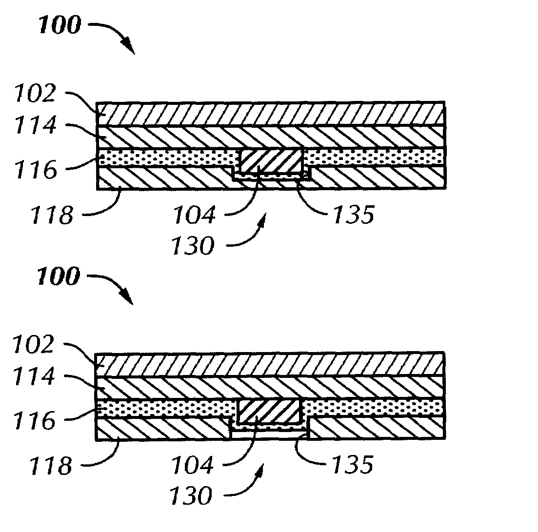
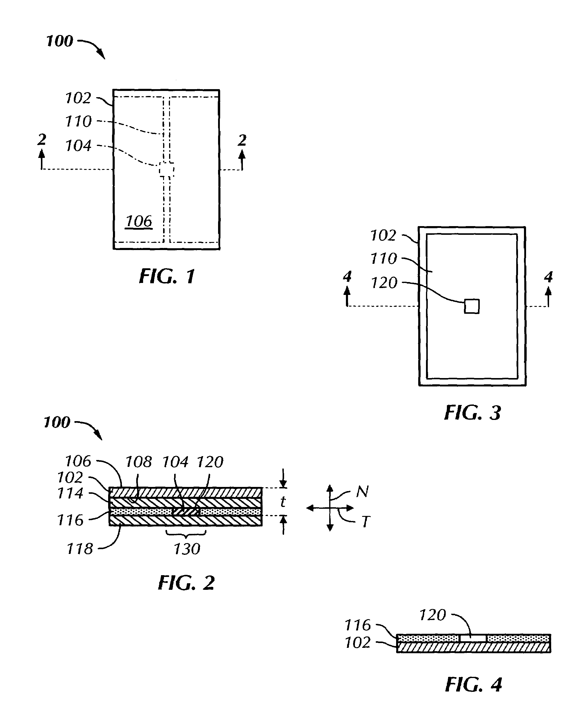
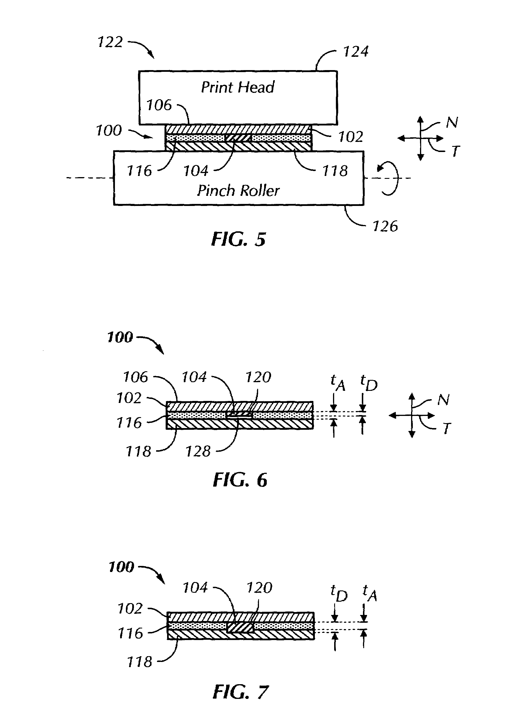
[0026]Referring more particularly to FIGS. 1 and 2 of the drawings, a radio-frequency identification (RFID) tag 100 includes a face stock 102 and an RFID device 104. The face stock 102 may be described as having a printable side or surface 106 and an inlay side or surface 108. The RFID device 104 is mounted to or disposed on the inlay side 108 of the face stock 102 and may include any type of RFID structure, including chips, straps, power source (for active devices), and connecting structure for coupling with an antenna 110, as known in the art.

[0027]The face stock 102 may include an inlay substrate 114, such as a layer of polyethylene terephthalate (PET), applied to the inlay side 108 on which the RFID device 104 (such as a microchip) and the antenna 110 may be disposed. In addition, a layer of adhesive 116, such as a pressure sensitive adhesive (PSA), may be coated on the inlay side 108 of the face stock 102, and a liner 118 may be releasably adhered to the layer of adhesive 116.

[...


PUM


Abstract

A radio-frequency identification (RFID) tag includes a face stock and an RFID device. The face stock has a printable side and an inlay side, with the RFID device mounted to the inlay side. A layer of adhesive is coated on the inlay side of the face stock. A liner is releasably adhered to the layer of adhesive and includes a relief area that accommodates for defection of the RFID device. The accommodation of the thickness of the RFID device results in a tag that has a substantially uniform printable surface. Accordingly, when passing through a printer, the printable surface is maintained substantially flat or linear at the print head of the printer, thereby minimizing jamming and enhancing printability. A pinch roller for a printer also accommodates for deflection of the RFID tag by providing a deformable section along a length thereof the body that has a greater resiliency than the rest of the body. At the location of the RFID device, the layer of adhesive may also include a blank that is substantially free of adhesive for accommodating the RFID device.

Description

FIELD OF THE INVENTION[0001]The present invention relates to radio-frequency identification (RFID) tags. The invention also relates to RFID tags with enhanced printing capabilities.BACKGROUND OF THE INVENTION[0002]Conventional RFID tags have a substrate or face stock on one side of which an RFID device, chip, or strap is mounted. An adhesive layer is coated over the RFID device, and a release liner is applied to the adhesive layer. Accordingly, there is an uneven thickness in the RFID tag at the location of the RFID device, chip, or strap, such that the RFID tag bulges at this location.[0003]It is common to print information on the RFID tag after the tag has been manufactured, either by the manufacturer or by the end user. However, because of the uneven thickness, when passing through a printer during a printing process, the RFID tag has a tendency to jam in the printer or to otherwise present an undesirable printing surface for the print head of the printer, thereby resulting in pr...

Claims


Application Information

Patent Timeline
Patent Type & Authority Patents(United States)
IPC IPC(8): G06K19/06G06K15/00H04Q5/22G08B13/14G06K5/00G06K19/00
CPCG06K19/07749G06K1/121
Inventor FORSTER, IAN JAMESFERGUSON, SCOTT WAYNE
Owner AVERY DENNISON CORP
Why Eureka
Try Eureka