Dispenser and dispensing system for radar jamming material

a technology of dispensing system and radar, which is applied in the direction of ammunition projectiles, weapons, projectiles, etc., can solve the problems of spooling jams, roving bundles losing structural support, and heavy weight, so as to reduce the frequency of jams, reduce the effect of jams and reducing the size of the roving bundl

Active Publication Date: 2019-06-25
VERTEX AEROSPACE LLC
View PDF43 Cites 2 Cited by
  • Summary
  • Abstract
  • Description
  • Claims
  • Application Information

AI Technical Summary

Benefits of technology

[0007]The apparatus and systems described herein are directed to material dispensing applications, designed to minimize jams in unspooling countermeasure and / or area suppression material, such as chaff rovings. The implementations are configured to store for dispensing spools or bundles of the material horizontally with respect to the vehicle in or on which they are mounted, and with respect to ground and normal to the Earth's gravitational force. One or more material bundle may be mounted on a horizontal support rod, from which the materials may be unspooled, reducing jam frequency and making easier dispensing to a cutting mechanism.
[0010]Both ends of the canister may be rotatably engaged with the support rod, or just the first end. The support rod may terminate at, or traverse, the ends. In some implementations, the rod may be connected to the second end in a fixed manner, in which case the second end and rod rotate together with respect to the first end, or vice versa. One or both of the ends may comprise end caps including bearings facilitating the respective rotational relationships.
[0011]Implementations also provide a material dispensing system comprised of the dispenser described above, operably engaged with a material roving cutting unit. The cutting unit may be motorized to draw material rovings from one or more canisters in the dispensing unit. As a result of the winding design typical of area suppression and countermeasure materials, such as chaff bundles, the unspooling force exerted by the cutting unit to draw the roving translates into rotational forces on the chaff bundles and results in a rotational spin of either the rod bearing the weight of the chaff bundle, or each canister end having an aperture through which the roving is being drawn. The tensile strength of commercially available area suppression and countermeasure materials is sufficient such that the materials will not break under such unspooling forces.
[0012]The cutting unit may include a rotatable cutting head configured with one or more blades disposed across a surface of the cutting head, the blades being spaced apart so as to cut the drawn roving(s) into desired lengths. The cutting head is disposed adjacent to a rotatable roller such, when the cutting head and roller are rotating, a surface of the roller periodically comes into contact with the respective edges of the cutting head blades in order to cut threaded rovings into desired lengths. A drive structure operably engaged with the cutting head and roller provides rotational motive forces sufficient to draw the rovings there between and to cut the rovings into desired lengths. Cutting heads with distinct spacing of cutting blades may be interchanged into the cutting unit, so the lengths into which the rovings will be cut may be selectable. Certain implementations may be further configured with a support rod drive structure, synchronized with the cutting unit, for assisting in providing rotational forces to the support rod bearing the weight of the material bundle.

Problems solved by technology

Some chaff dispensing systems have been employed that cut chaff dipoles in-flight, but they typically are bulky, heavy and have a relatively slow response time.
The vertical orientation often results, due to a roving bundle's weight (e.g., approximately 50 pounds for common roving bundles) in compression forces that cause the roving bundle to lose its structural support leading to spooling jams when the chaff may be critically needed.
Vertical stacking of multiple chaff bundles on top of one another would only exacerbate this fault mode.
Thus, conventional in-flight chaff dispensing systems present a number of problems, and an improved self-protection device has been needed for some time.

Method used


Image

  • Dispenser and dispensing system for radar jamming material
  • Dispenser and dispensing system for radar jamming material
  • Dispenser and dispensing system for radar jamming material

Examples


Embodiment Construction

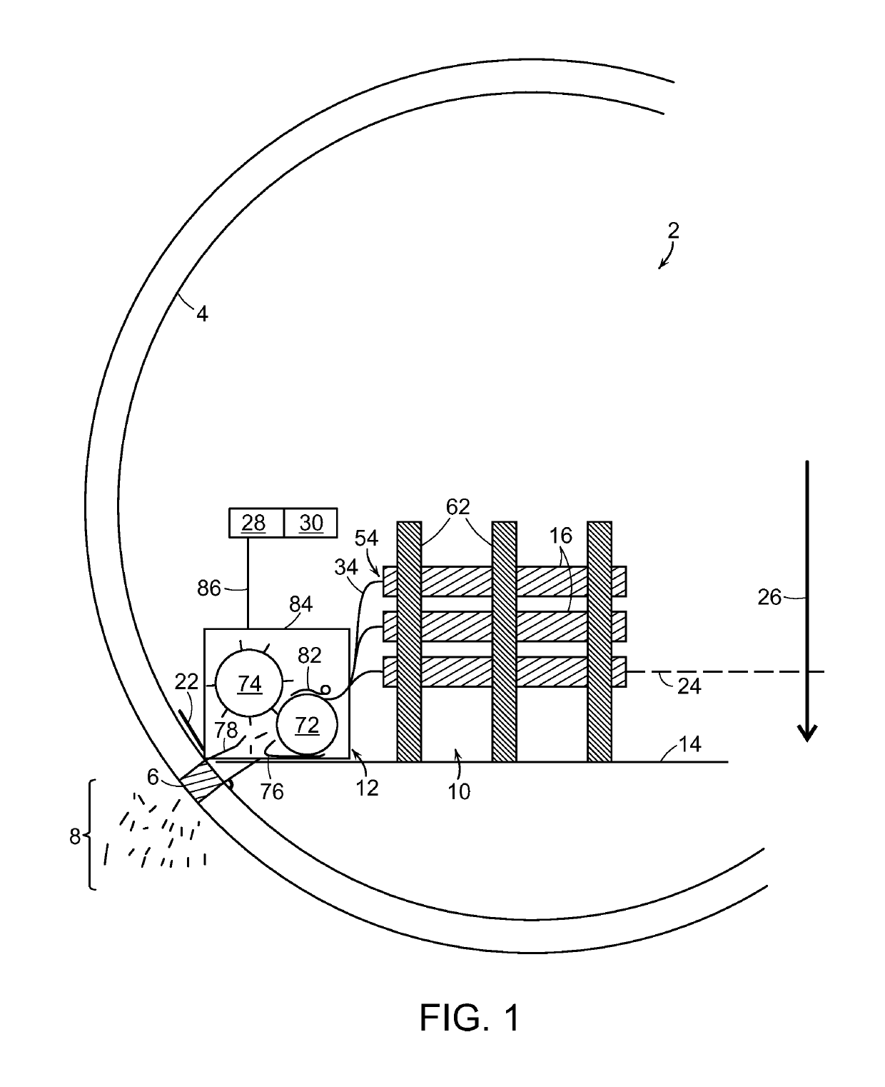
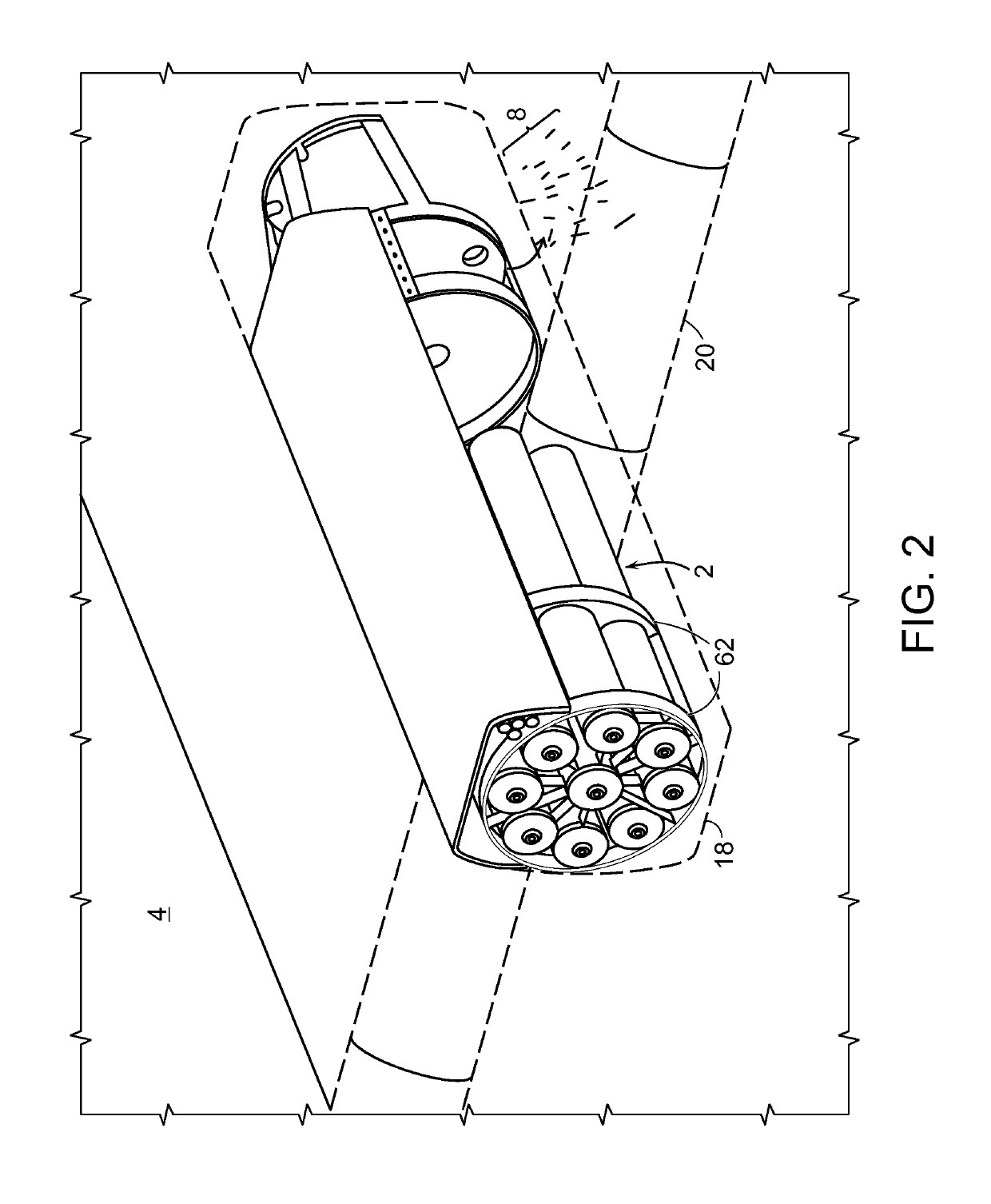
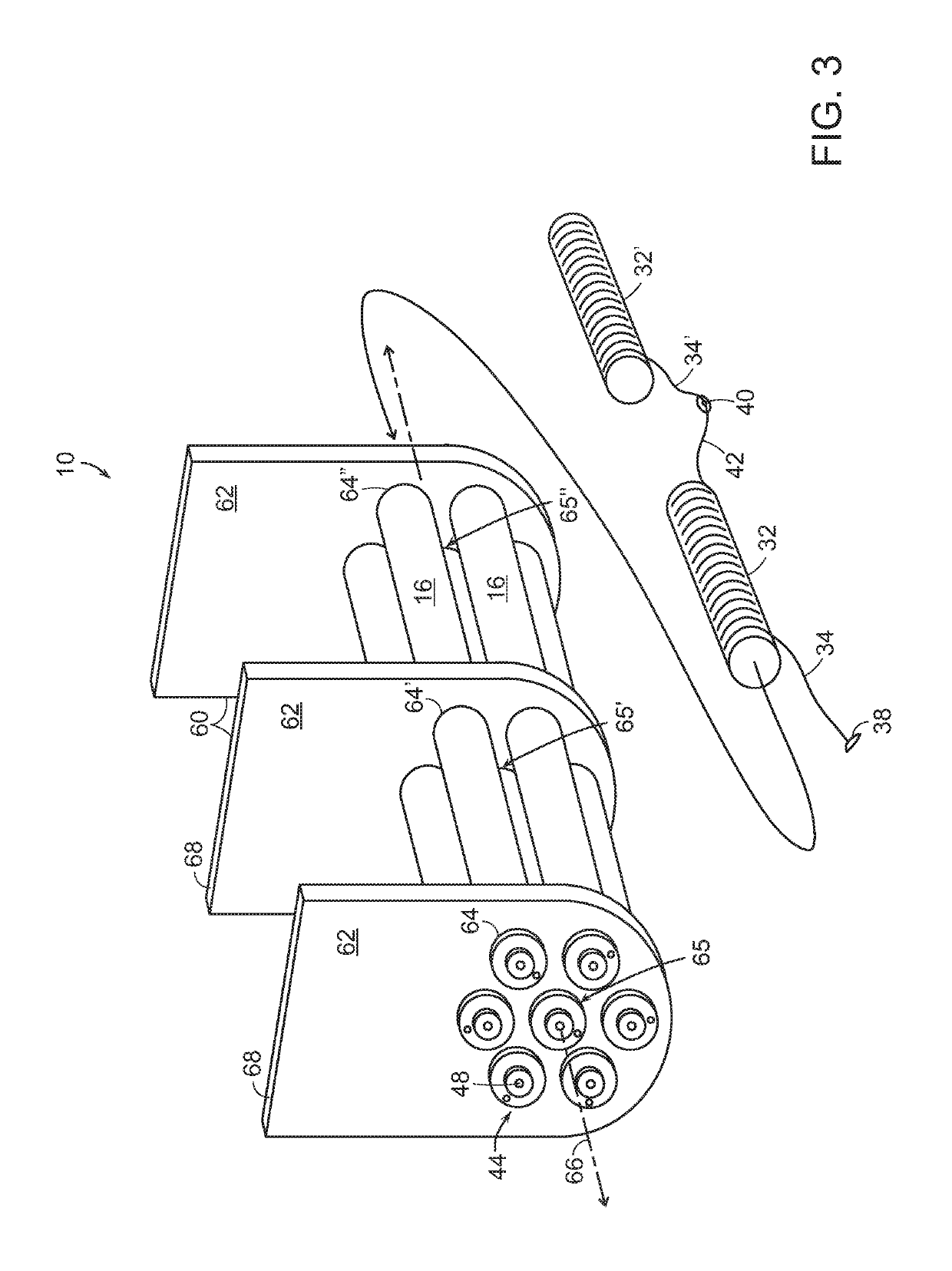
[0020]The implementations described herein are directed to dispensing systems particularly useful for in-flight cutting and dispensing of area suppression and / or countermeasure materials. Such materials may comprise, but are not limited to, “chaff”, glass fibers or filaments (e.g. 1 mil diameter) coated with electrically conducting aluminum or other suitable metal, or graphite fibers, hot IR chaff, or other materials that provide reflection or absorption of radiofrequency energy sufficient to confuse and divert radar based missiles aimed at the aircraft, or to create a radar-suppressing cloud dispersing and lingering over a wide area. The dispensed material may include any materials that may be cut into discrete segments, sections, particles, or other subdivided form, for dispensing into an environment in which the material may be useful, e.g., for combating measures directed at or against persons, vehicles, installations, etc., or for preemptive area suppression of radar such as mi...


PUM


Abstract

A dispensing unit and system for area suppression and / or countermeasure materials includes at least one canister with two ends, a support rod including a portion extending between the ends along an axis rotatably engaged with the first end, a wall defining a cavity for housing at least one material bundle, an aperture in the first end for dispensing material from the bundle, and a support structure providing horizontal support for the at least one canister. Dispensing systems include a roving cutting mechanism.

Description

STATEMENT REGARDING FEDERALLY SPONSORED RESEARCH[0001]This invention was made with Government support under Contract No. H94003-04-D-0006 awarded by the United States Department of Defense. The Government has certain rights in this invention.FIELD[0002]This invention relates to systems for in-flight dispensing and cutting of adversarial radar area suppression and countermeasure materials, such as chaff dipole elements, for the protection of aerial vehicles against guided missiles and other radar-based weaponry.BACKGROUND[0003]Controllably deployable area suppression and countermeasure materials of several types are used to deter and defeat attacks on aircraft by other aircraft, missiles, and antiaircraft artillery. In each case, the material is deployed by an aircraft to confuse an attacker, and specifically the sensor used by the attacker, creating a radar-jamming cloud.[0004]A conventional method for the self-protection of aircraft and the like from radar-guided missiles employs a...

Claims


Application Information

Patent Timeline
Patent Type & Authority Patents(United States)
IPC IPC(8): F42B12/70
CPCF42B12/70
Inventor FIX, MARTIN G.STREIB, STEPHEN A.
Owner VERTEX AEROSPACE LLC
Why Eureka
Try Eureka