Determination of elastomer material properties for the Mullins effect using a bi-axial test device

a test device and elastomer technology, applied in the direction of fluid tightness measurement, simultaneous indication of multiple variables, instruments, etc., can solve the problems of difficult analytical and experimental studies, material properties obtained from one-dimensional tests may not represent true behaviors, and few analytical and experimental studies have been attempted to determine non-elastic properties of elastomers

Active Publication Date: 2009-05-19
ANSYS
View PDF10 Cites 13 Cited by
  • Summary
  • Abstract
  • Description
  • Claims
  • Application Information

AI Technical Summary

Benefits of technology

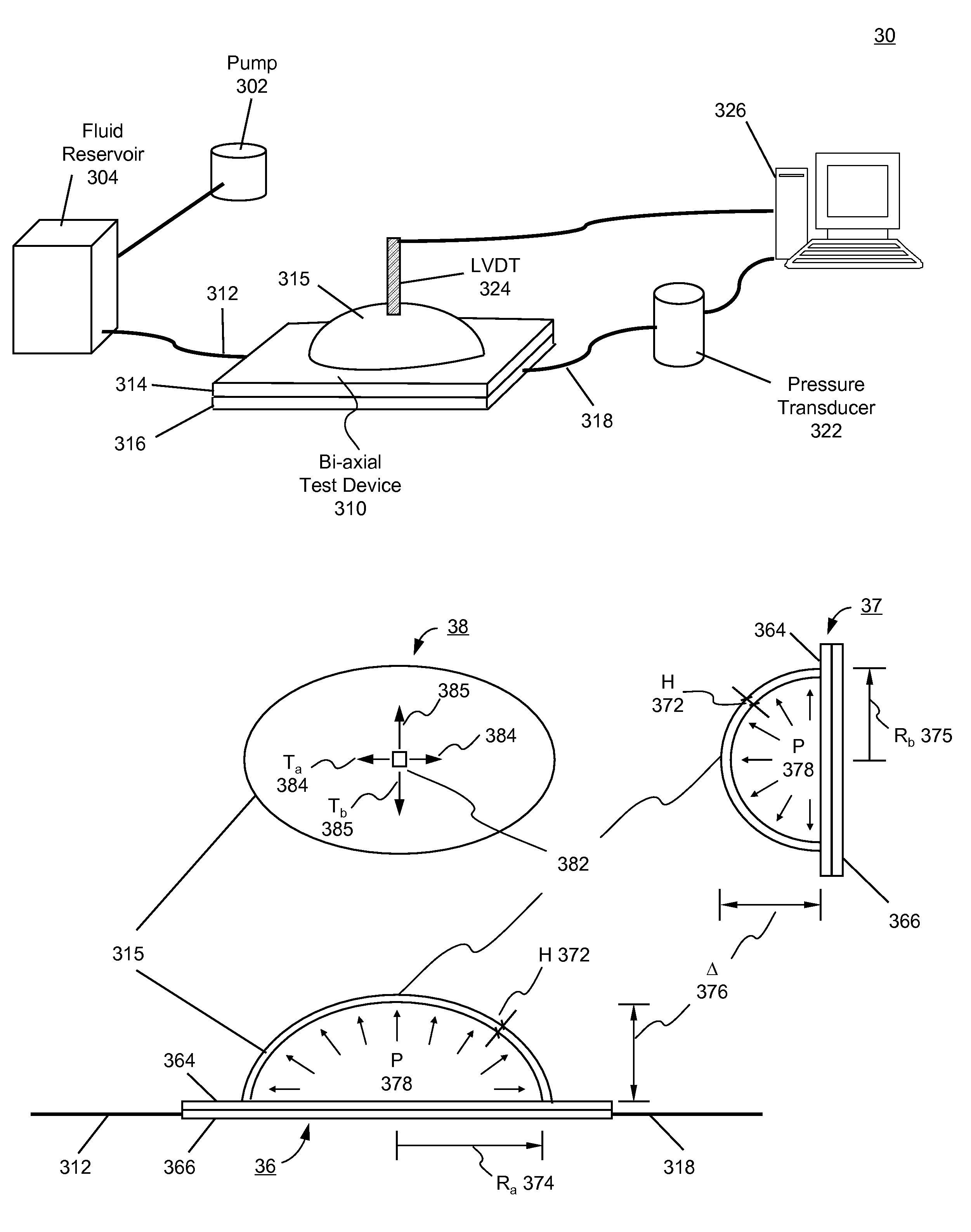
[0015]According to one embodiment, the present invention is a bi-axial test device for determining elastomer material properties for the Mullins effect under bi-axial tension, the device comprises at least the following: a top plate having a circular opening, the circular opening having a diameter; a bottom plate having an inflating fluid intake and an inflating fluid outlet; and a plurality of connecting means for coupling the top and bottom plate.
[0016]According to another embodiment, the present invention is a system for determining elastomer material properties for the Mullins effect under bi-axial tension, the system comprises at least the following: a bi-axial test device having

Problems solved by technology

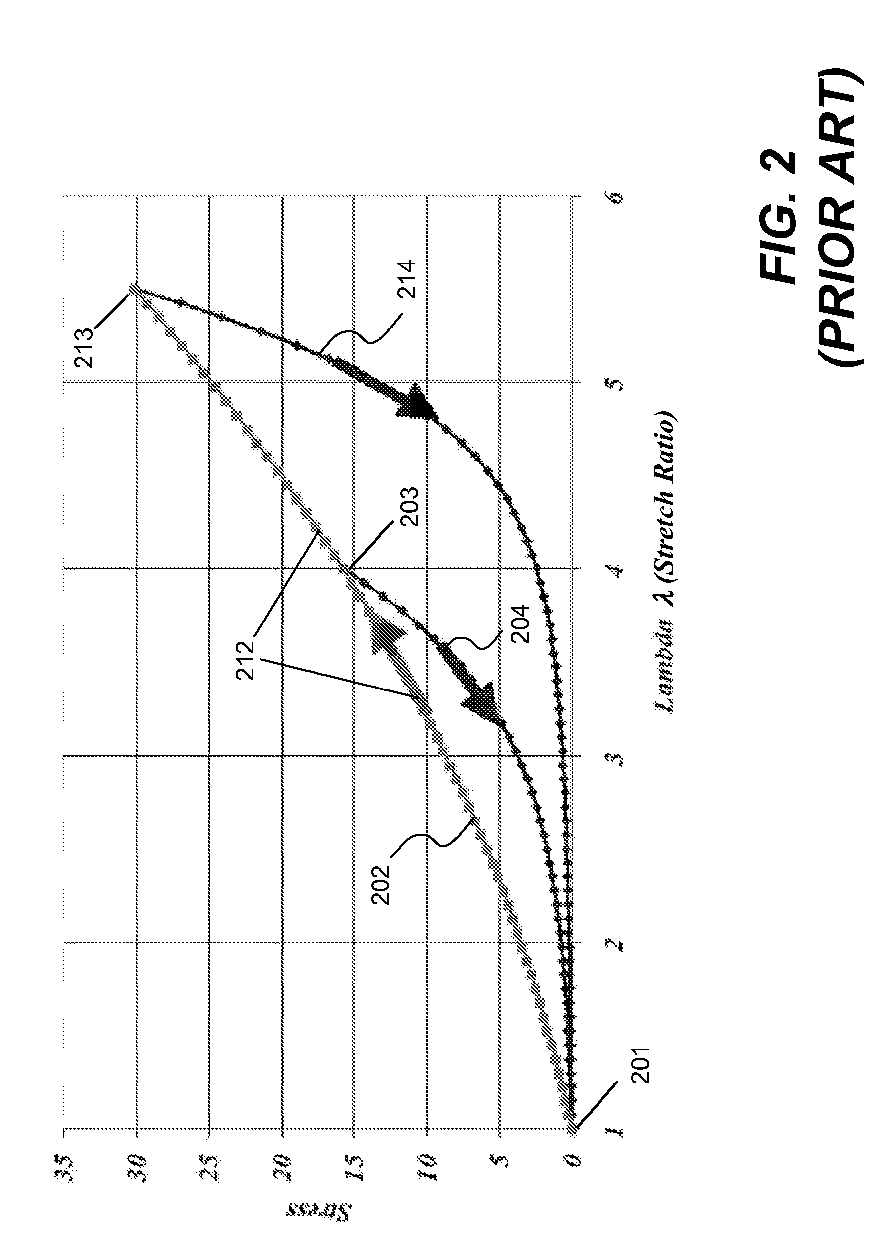
To date, very few analytical and experimental studies for determining non-elastic properties of elastomers have been attempted.
The additional effects and the lack of an adequate constitutive equation that describes these phenomena make the analytical and experimental studies very difficult.
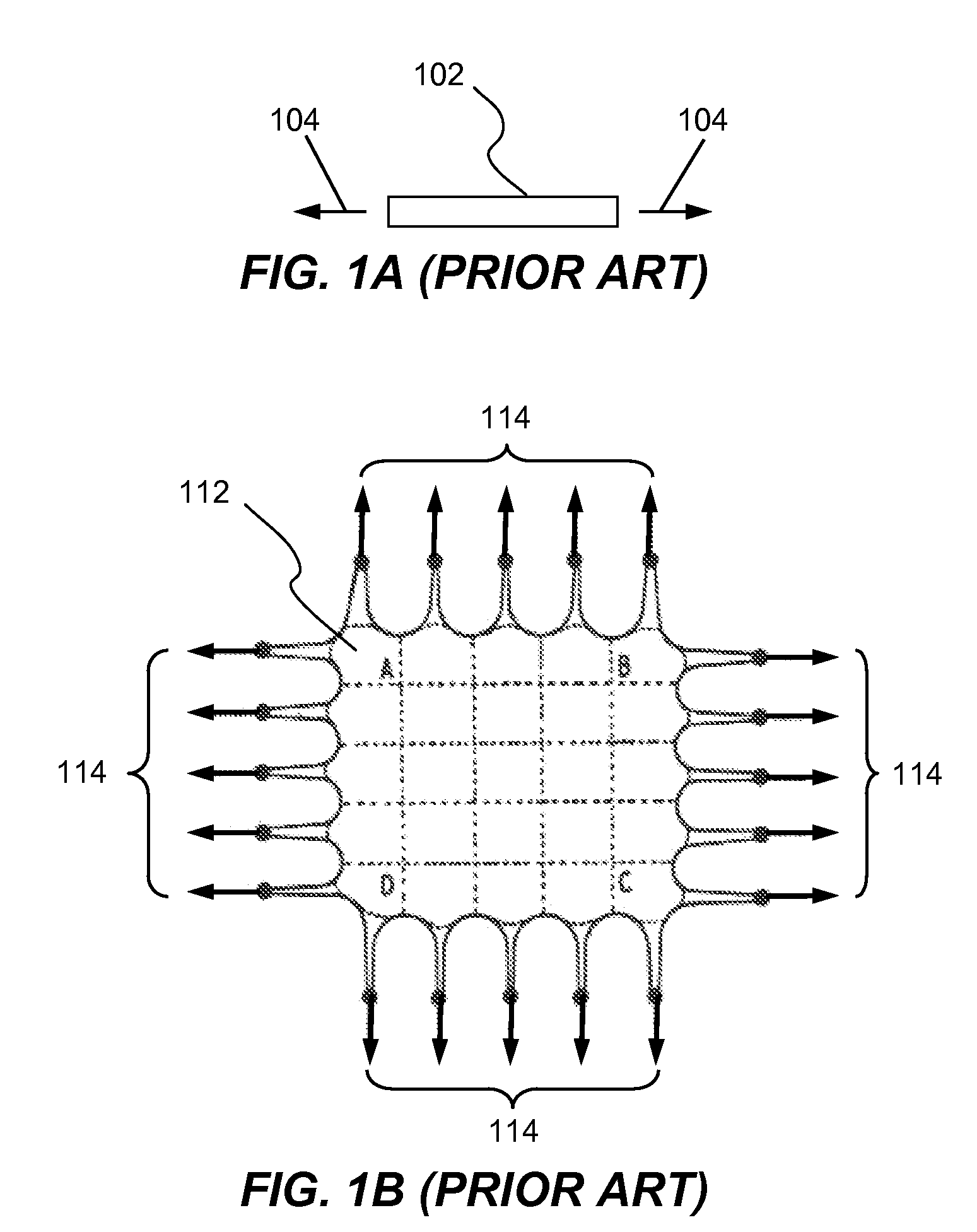
However, the material properties obtained from the one-dimensional test may not represent true behaviors of elastomer contained in a structure, which is generally not in a one-dimensional space.
However, this prior art approach require

Method used


Image

  • Determination of elastomer material properties for the Mullins effect using a bi-axial test device
  • Determination of elastomer material properties for the Mullins effect using a bi-axial test device
  • Determination of elastomer material properties for the Mullins effect using a bi-axial test device

Examples


Embodiment Construction

[0034]In the following description, numerous specific details are set forth in order to provide a thorough understanding of the present invention. However, it will become obvious to those skilled in the art that the present invention may be practiced without these specific details. The descriptions and representations herein are the common means used by those experienced or skilled in the art to most effectively convey the substance of their work to others skilled in the art. In other instances, well-known methods, procedures, components, and circuitry have not been described in detail to avoid unnecessarily obscuring aspects of the present invention.

[0035]Reference herein to “one embodiment” or “an embodiment” means that a particular feature, structure, or characteristic described in connection with the embodiment can be included in at least one embodiment of the invention. The appearances of the phrase “in one embodiment” in various places in the specification are not necessarily ...


PUM


Abstract

Systems and methods for determining material properties of elastomers for the Mullins effect are described. In one aspect of the present invention, material properties of an elastomer membrane specimen are obtained using a system comprising a bi-axial test device, a pump, a fluid reservoir, a linear variable differential transformer, a pressure transducer and a computer. The bi-axial test device comprises a top plate and a bottom plate. The top plate has an elliptical shape hole configured to allow the specimen to be expanded up by pressures of the inflating fluids. The hole is so dimensioned that the specimen can be expanded with a relatively low pressure. The bottom plate is a solid plate configured with a fluid intake at one side and a fluid outlet at the other end. The fluid intake is connected to the fluid reservoir. Fluids stored in the fluid reservoir are pumped into the bi-axial test device by the pump. The fluid outlet is connected to the pressure transducer.

Description

CROSS-REFERENCE TO RELATED APPLICATIONS[0001]This application is a continuation-in-part of co-pending U.S. patent application Ser. No. 11 / 746,039 for “Determination of elastomer material properties for the Mullins effect using a bi-axial test device”, filed on May 8, 2007.FIELD OF THE INVENTION[0002]The present invention generally relates to determination of rubber-like material properties, more particularly to methods and systems for determining the material properties of elastomers for the Mullins effect using a bi-axial test device.BACKGROUND OF THE INVENTION[0003]Rubber-like materials such as elastomers have been used in many parts and structures in various industries (e.g., automotive, aerospace, etc.) for years. But the mechanical properties (e.g., stress-strain or stress-stretch ratio relationship) of elastomer, other than the elastic properties, are still not clearly defined; hence, designs and analyses (especially used in computer-aided engineering) of these structures are ...

Claims


Application Information

Patent Timeline
IPC IPC(8): G01N3/10G01D1/16
CPCG01N3/10G01N2203/0282
Inventor FENG, WILLIAM WHALLQUIST, JOHN O.
Owner ANSYS
Why Eureka
Try Eureka