Exhaust valve arrangement and a fuel system incorporating an exhaust valve arrangement

a technology of exhaust valve and fuel system, which is applied in the direction of oscillatory slide valve, non-mechanical valve, machine/engine, etc., can solve the problems of preventing the flow of exhaust gas, and achieve the effect of reducing impact noise and wear, reducing noise, and reducing nois

Inactive Publication Date: 2009-05-19
DELPHI INT OPERATIONS LUXEMBOURG S A R L
View PDF12 Cites 66 Cited by
  • Summary
  • Abstract
  • Description
  • Claims
  • Application Information

AI Technical Summary

Benefits of technology

[0010]A further advantage of the invention is that the flow of exhaust gas through the open valve arrangement into the exhaust passage is not obstructed. In a conventional arrangement, where the exhaust valve opens into the combustion chamber, the head of the valve and its stem tend to impede the exhaust gas flow. The cylinder head exhaust valve bore can therefore be machined with a smaller diameter than conventional systems, if desired, whilst still allowing the same exhaust flow. Furthermore, with an outwardly opening exhaust valve arrangement there is no requirement to form clearance cut-outs in the piston crown or fire deck which may otherwise disrupt in-cylinder air swirl to the detriment of efficient combustion.
[0011]Preferably, the piston cooperates with the outer sleeve so as to urge the outer sleeve into the closed position in which it closes the exhaust passage. In one example, a piston spring serves to urge the piston into a position in which the piston holds the outer sleeve closed against the seat. With the piston in this position, its lower surface lies flush with a fire deck (ceiling) of the combustion chamber, which is defined by the cylinder head.
[0012]In another embodiment, a gas or fluid pressure may act on the piston to urge the piston into a position in which the piston holds the outer sleeve closed.
[0013]In an alternative embodiment a “wave washer” or similar is provided between the piston and the outer sleeve so as to minimise impact noise and wear. Alternatively, a compliant material may be substituted which both minimises impact noise and provides a seal between the piston and the outer sleeve to minimise compression gas leakage past the piston when they are in the rest position.
[0014]In a particularly preferred embodiment, the piston is hollow. A hollow piston is relatively lightweight. In addition, as the piston is hollow, it can be at least partially filled with a heat transfer material (e.g. sodium salts) which serves to aid heat transfer away from the face of the piston that is exposed to the combustion chamber.
[0015]In one preferred embodiment, the piston includes a main piston body in the form of a cup and a piston cap. The piston cap closes the cup so that they are securely attached, one to the other. In this case the piston spring may act on the cap of the piston.

Problems solved by technology

In a conventional arrangement, where the exhaust valve opens into the combustion chamber, the head of the valve and its stem tend to impede the exhaust gas flow.

Method used


Image

  • Exhaust valve arrangement and a fuel system incorporating an exhaust valve arrangement
  • Exhaust valve arrangement and a fuel system incorporating an exhaust valve arrangement
  • Exhaust valve arrangement and a fuel system incorporating an exhaust valve arrangement

Examples


Embodiment Construction

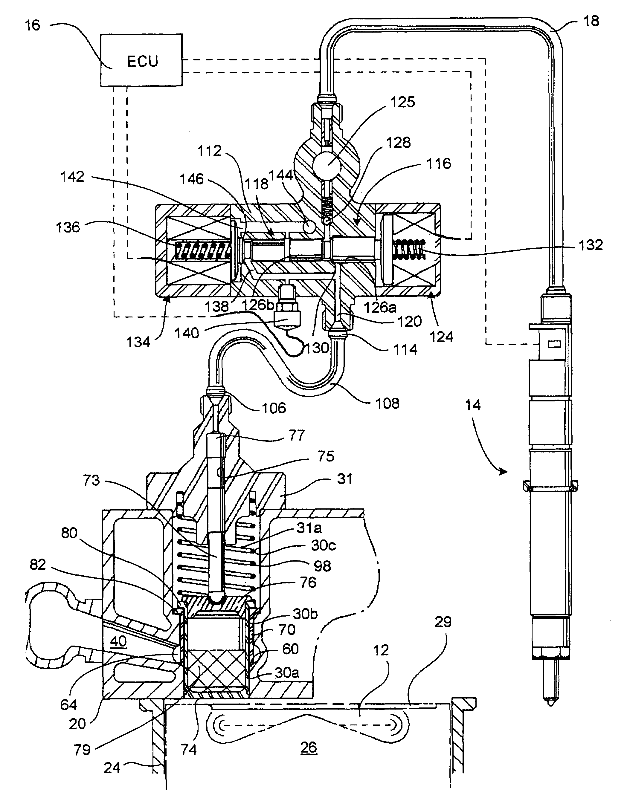
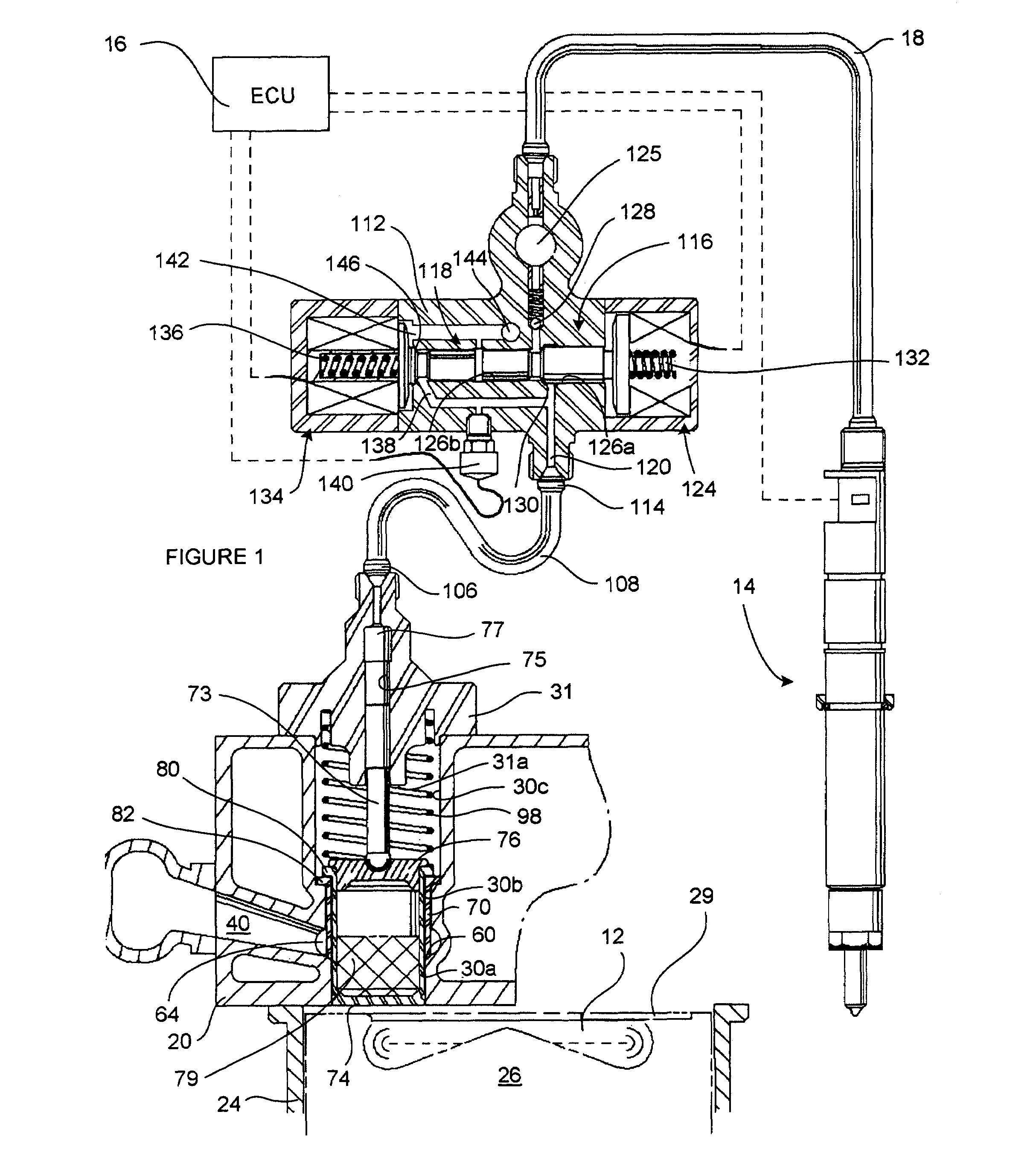
[0059]Referring to FIG. 1, an engine cylinder for an internal combustion engine of the compression ignition (diesel) type defines a combustion chamber 12 into which combustible fuel is injected. In general, the engine is provided with a plurality of cylinders, but for simplicity only one of the cylinders will be described here. The combustion chamber 12 has an associated fuel injector 14 which is arranged to inject fuel at relatively high pressure into the combustion chamber 12 under the control of an Engine Control Unit (ECU) 16. The injector 14 receives pressurised fuel for injection through from a supply passage 18.

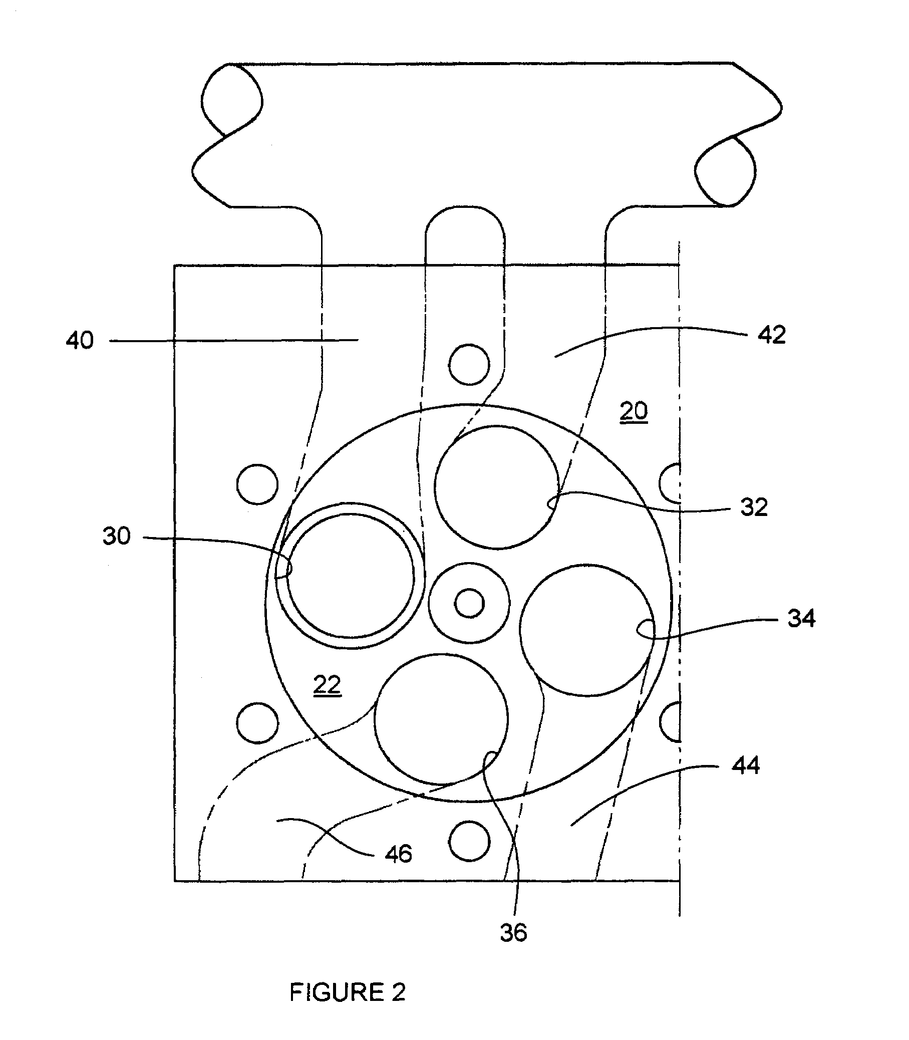
[0060]The engine cylinder has a cylinder head 20 which defines an upper ceiling of the combustion chamber 12, typically referred to as the fire deck 22. A cylinder piston 26 is driven, in use, by a crank shaft of the engine within a cylinder sleeve 24. The cylinder piston 26 is provided with a recess or crown in its upper surface to define a piston bowl which forms a l...


PUM


Abstract

An exhaust valve arrangement for use in a combustion chamber of a compression ignition internal combustion engine, includes a piston which is movable outwardly from the combustion chamber in response to pressure generated within the combustion chamber as a result of combustion, and an outer sleeve within which the piston is movable. The outer sleeve is an exhaust valve which is actuable between open and closed positions to open and close, respectively, an exhaust passage from the combustion chamber. The exhaust valve arrangement further includes a pump chamber for receiving fluid, and a pumping plunger coupled to the piston and movable with the piston so as to pressurise fluid (e.g. fuel) within the pump chamber as the piston is urged outwardly from the combustion chamber. The pressure within the pump chamber is proportional to cylinder pressure and is sensed by a sensor which provides an output signal to an Engine Control Unit (ECU 16). An accumulator volume receives fluid that is pressurised within the pump chamber. Where the fluid is fuel, the accumulator volume is arranged to deliver fuel to one or more injectors of a common rail fuel injection system. Alternatively the accumulator volume may be arranged to deliver pressurised fluid to one or more engine systems e.g. for actuation purposes.

Description

TECHNICAL FIELD[0001]The invention considers improvements relating to combustion engine technology and, in particular, compression ignition (diesel) internal combustion engine technology. It is a particular feature of the invention to provide an improved fuel system incorporating an improved exhaust valve arrangement. The invention also relates to the exhaust valve arrangement itself.BACKGROUND TO THE INVENTION[0002]During the combustion cycle of the engine, a piston reciprocates in known fashion within a cylinder which defines a combustion chamber into which an injection of fuel is provided to initiate the combustion process. The combustion chamber is closed, at its upper end, by a cylinder head which defines a so-called fire deck of the cylinder. Current diesel engines are likely to have four valves per cylinder; two intake valves and two exhaust valves. The valves normally take the form of mushroom-headed poppet valves which, when closed, seat against the fire deck of the cylinde...

Claims


Application Information

Patent Timeline
Patent Type & Authority Patents(United States)
IPC IPC(8): F02M37/12F02M37/14F01L9/10
CPCF01L7/02F01L9/02F02M59/107F02M63/0225F02M63/0265F01L9/10
Inventor DINGLE, PHILIP J. G.
Owner DELPHI INT OPERATIONS LUXEMBOURG S A R L
Why Eureka
Try Eureka