Hybrid motor vehicle driveline

a hybrid motor vehicle and driveline technology, applied in mechanical devices, transportation and packaging, gearing, etc., can solve the problems of jerking, reconnection may be felt by the driver as an unacceptable jerk, and the driver may still feel the jerk when the first clutch is applied, so as to increase the inertia and frictional drag

Active Publication Date: 2009-05-19
FORD GLOBAL TECH LLC
View PDF15 Cites 67 Cited by
  • Summary
  • Abstract
  • Description
  • Claims
  • Application Information

AI Technical Summary

Benefits of technology

[0013]Hence the electric motor is employed to spin the propshaft up from rest (while in the two wheel drive mode) to a rotational speed which, preferably, matches the speed of the engine and the rear wheels before reconnection of the auxiliary driveline to the engine and the rear wheels occurs. This ensures that the changeover to four wheel drive is achieved without any noticeable jerk. Furthermore, the electric motor can spin the propshaft up to the predetermined speed very quickly compared with the known arrangement described above.

Problems solved by technology

During two wheel drive conditions, the driveline components connected to the rear wheels may be caused to rotate due to frictional drag between the components in the driveline.
However, a problem with dynamic driveline reconnection is that the reconnection may be felt by the driver as an unacceptable “jerk”, i.e. a spasmodic acceleration.
A problem with this known arrangement is that a jerk may still be felt when the first clutch re-engages.
Further, there is a delay in transferring from two wheel drive to four wheel drive while the partially reconnected driveline is spinning up.

Method used


Image

  • Hybrid motor vehicle driveline
  • Hybrid motor vehicle driveline
  • Hybrid motor vehicle driveline

Examples


second embodiment

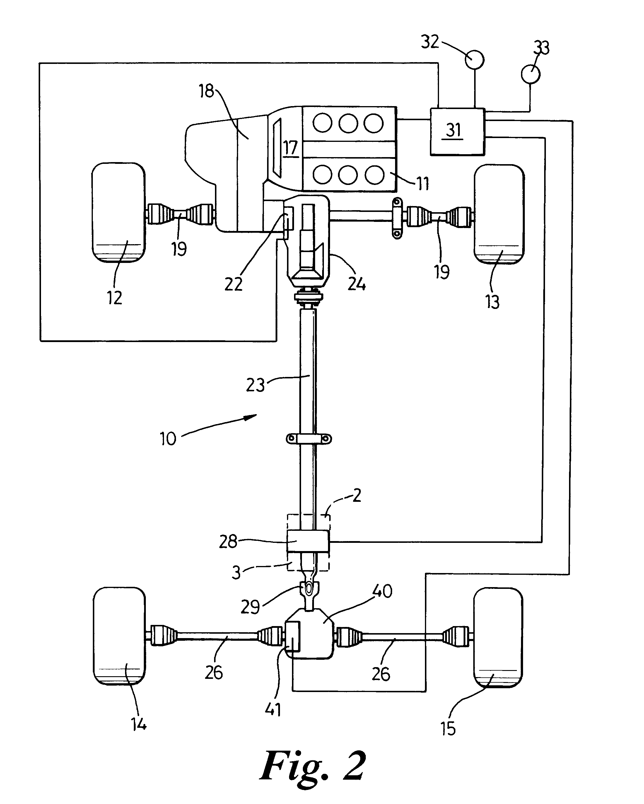
[0042]In the alternative arrangement of FIG. 2 those components common to the components of FIG. 1 bear the same reference numerals. In this second embodiment there is no clutch provided between the propshaft and the differential. Instead the propshaft 23 is directly connected via the universal joint 29 to a free-running differential 40. The propshaft 23 is decoupled from (and reconnected to) the rear wheels 14, 15 by the action of a clutch mechanism 41 incorporated within the differential 40. This clutch mechanism 41 is under the control of the controller 31.

[0043]This second embodiment operates in a similar fashion to that of the first with the electric motor 28 spinning up the propshaft 23, transmission 24 and those components of the differential 40 which are not isolated by the action of the clutch 41 to the appropriate rotational speed prior to the change to four wheel drive capability through the engagement of the PTO clutch 22 and differential clutch 41.

[0044]The embodiment o...

third embodiment

[0046]This third embodiment provides the maximum fuel economy benefit while the vehicle is in two wheel drive mode because the transmission 24, the propshaft 23, the differential 25 and the rear drive shafts 26 are all stationary.

[0047]On changing over to four wheel drive mode, the electric motor 28 spins up the propshaft 23 (and the connected driveline components) to the appropriate speed and subsequently, the controller 31 initiates re-engagement of the PTO clutch 22 and hub clutches 50.

[0048]This embodiment is capable of operating as a hybrid vehicle in four wheel drive mode.

fourth embodiment

[0049]In FIG. 4, those components common to the components of FIG. 1 bear the same reference numerals. In this alternative embodiment, the electric motor 28 is housed within the differential 42 and connected to a crown wheel 43. A clutch 44 incorporated in the differential 42 serves to isolate the crown wheel 43, and propshaft 23 from the drive shafts 26 when the vehicle is in two wheel drive mode.

[0050]On changing over to four wheel drive, the electric motor 28 spins up the crown wheel 43 and the propshaft 23 to the appropriate speed. Then the controller 31 initiates re-engagement of the PTO clutch 22 and the differential clutch 44.

[0051]This configuration shown in FIG. 4 allows a hybrid drive capability in two wheel drive or four wheel drive mode.

[0052]In the further alternative arrangement of FIG. 5, those components common to the components of FIG. 4 bear the same reference numerals. Two further clutches are incorporated in the differential to enhance the hybrid drive capability...


PUM


Abstract

A hybrid motor vehicle (10) has a four wheel drive arrangement in which the front wheels (12 and 13) are driven by the engine (11) in two wheel drive mode and all four wheels (12-15) in four wheel drive mode. The engine is connected to the rear wheels (14 and 15) through an auxiliary driveline which includes a first clutch (22) to connect to the engine (11), a propshaft (23) and a differential (25). An electric motor (28) is connected to the propshaft (23) for the purpose of driving the vehicle either with or without the assistance of the engine (11). A second clutch (27) is located between the propshaft (23) and the differential (25). When the vehicle is in two wheel drive mode, the propshaft (23) is disconnected from both the engine (11) and the rear wheels (14 and 15) and on switching to four wheel drive mode when the vehicle is moving the propshaft (23) is firstly spun up to a speed matching that of the engine (11) and rear wheels (14, 15) by the action of the electric motor (28). Then the auxiliary driveline (21) is reconnected by engaging the first and second clutches (22, 27). This reduces any acceleration jerk perceived by the driver.

Description

BACKGROUND OF THE INVENTION[0001]This invention relates to drivelines for hybrid motor vehicles and in particular for motor vehicles such as all terrain vehicles which have selective two wheel drive or four wheel drive.[0002]A hybrid motor vehicle is one which is equipped with a primary mover, such as an internal combustion engine and a secondary mover, such as an electric motor.[0003]There are various known ways in which the primary and secondary movers can be arranged in order to drive the vehicle and they may be arranged to drive either one axle or two.[0004]EP0584090 discloses a hybrid vehicle having permanent four wheel drive. The vehicle is provided with an internal combustion engine and an electric motor. The electric motor is combined with the rear differential and can provide drive to the front wheels via a drive shaft and to the rear wheels via the rear differential.[0005]It is also known to configure a hybrid vehicle so that it may be selectively driven either by the engi...

Claims


Application Information

Patent Timeline
Patent Type & Authority Patents(United States)
IPC IPC(8): B60K17/344B60K6/48B60K6/52
CPCB60K6/48B60K6/52B60K17/356B60K23/08B60W10/02B60W10/08B60L2240/421B60W20/00B60W2510/081B60W2520/28Y02T10/6221Y02T10/6265Y02T10/642Y02T10/62Y02T10/64B60W20/40
Inventor BURROWS, ANDREWBARLOW, ROB
Owner FORD GLOBAL TECH LLC
Why Eureka
Try Eureka