Automatic stop device and method for internal combustion engine

a technology of automatic stop device and internal combustion engine, which is applied in the direction of gearing control, gearing elements, and gearing vehicles, can solve the problems of burden on the mt vehicle and difficulty for an inexperienced driver, and achieve the effect of reducing the electric power distribution to the control member and improving fuel efficiency

Inactive Publication Date: 2009-05-19
TOYOTA JIDOSHA KK
View PDF14 Cites 0 Cited by
  • Summary
  • Abstract
  • Description
  • Claims
  • Application Information

AI Technical Summary

Benefits of technology

[0011]According to the present invention, the frictional engagement element is brought into the released state by the pressure generated by the operation of the operation unit. The pressure is maintained by stopping electric power distribution to the control member provided between the operation unit and the frictional engagement element. In other words, when electric power distribution to the control member is stopped after the frictional engagement element is brought into the released state, the frictional engagement element is maintained in the released state. After that, if a stop condition, which is at least the condition that the frictional engagement element is in the released state and the condition that an amount of electric power distributed to the control member is smaller than the predetermined value, is satisfied, the internal combustion engine is stopped. Accordingly, it is possible to perform idle stop while electric power distribution to the control member is reduced and the frictional engagement element is maintained in the released state. At that time, electric power distribution to the control member is reduced, and hence fuel efficiency can further be improved. Furthermore, the frictional engagement element is in the released state, and hence it is possible to prevent the vehicle from accidentally moving when the internal combustion engine is restarted. It is therefore possible to provide an automatic stop device for an internal combustion engine, the automatic stop device being capable of performing idle stop in a suitable manner.
[0013]According to the present invention, the frictional engagement element is brought into the released state by hydraulic pressure. When electric power distribution to the control member is stopped, the control member shuts off the oil passage connecting the operation unit and the frictional engagement element, so that the hydraulic pressure applied to the frictional engagement element is maintained. It is therefore possible to maintain the frictional engagement element in the released state. Accordingly, it is possible to prevent the vehicle from accidentally moving when the internal combustion engine is restarted, and perform idle stop in a suitable manner.
[0015]According to the present invention, the frictional engagement element is brought into the released state by the pressure generated by the operation of the operation unit. The pressure is maintained by stopping electric power distribution to the control member provided between the operation unit and the frictional engagement element. In other words, when electric power distribution to the control member is stopped after the frictional engagement element is brought into the released state, the frictional engagement element is maintained in the released state. After that, on conditions that it is determined that the frictional engagement element is in the released state and that it is determined that an amount of electric power distributed to the control member is smaller than the predetermined value, the internal combustion engine is stopped. Accordingly, it is possible to perform idle stop while electric power distribution to the control member is reduced and the frictional engagement element is maintained in the released state. At that time, electric power distribution to the control member is reduced, and hence fuel efficiency can further be improved. Furthermore, the frictional engagement element is in the released state, and hence it is possible to prevent the vehicle from accidentally moving when the internal combustion engine is restarted. It is therefore possible to provide an automatic stop method for an internal combustion engine, the automatic stop method being capable of performing idle stop in a suitable manner.

Problems solved by technology

An operation of such an MT vehicle is burdensome in performing a hill-start or in low-speed running, and is difficult for an inexperienced driver.
However, Japanese Utility Model Laying-Open No. 05-014664 does not describe that idle stop is performed in a suitable manner in a vehicle where a clutch is engaged or released independently of the clutch pedal.

Method used


Image

  • Automatic stop device and method for internal combustion engine
  • Automatic stop device and method for internal combustion engine
  • Automatic stop device and method for internal combustion engine

Examples


Embodiment Construction

[0020]An embodiment of the present invention will hereinafter be described with reference to the drawings. In the following description, the same parts are denoted by the same reference characters, and the names and functions thereof are the same. Accordingly, the detailed description thereof will not be repeated.

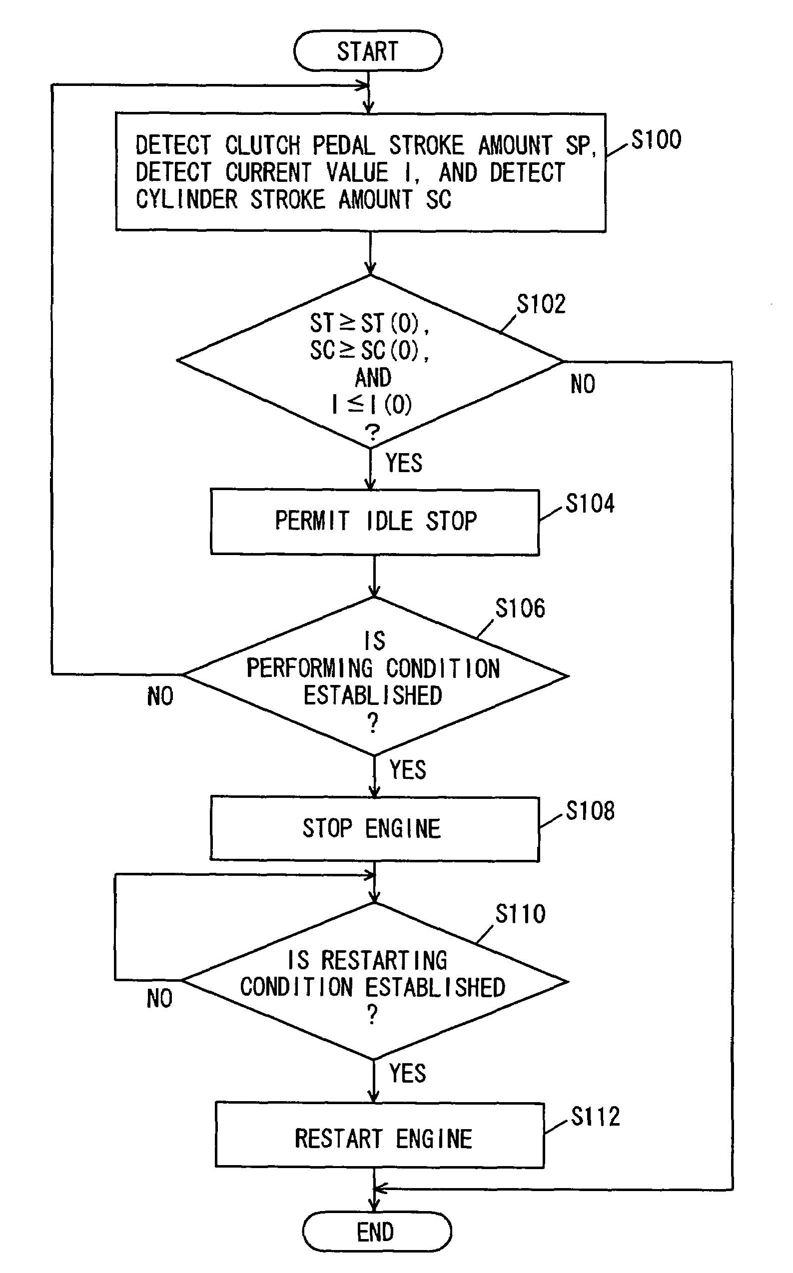
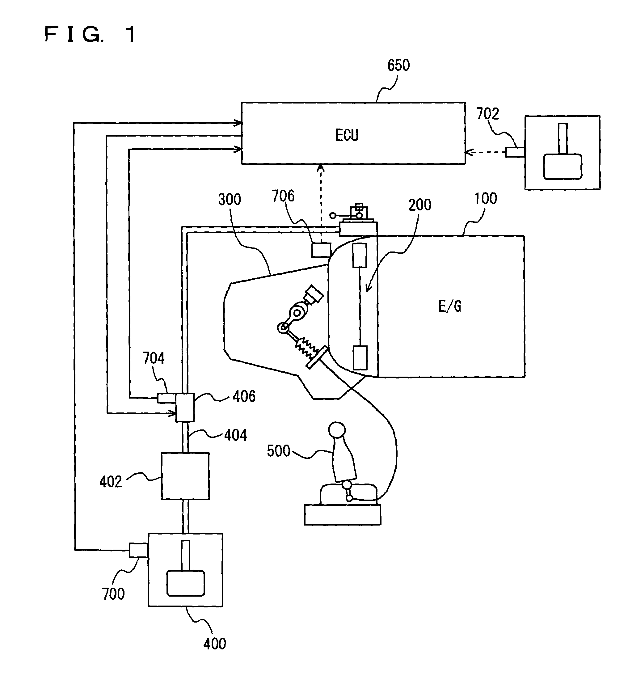
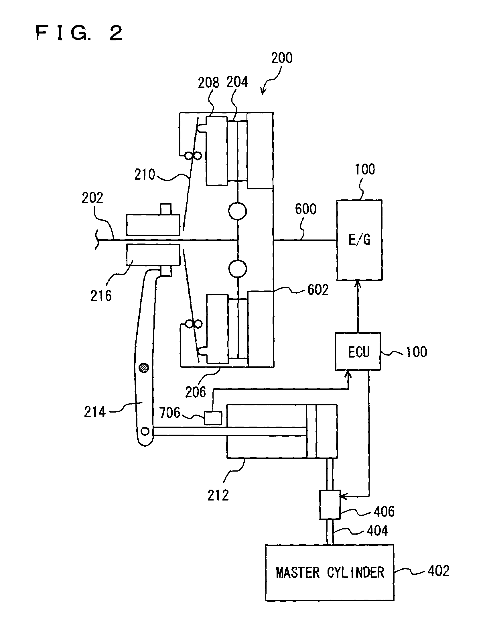
[0021]Referring to FIG. 1, a power train of a vehicle having an automatic stop device according to the embodiment of the present invention mounted thereon will be described. The power train includes an engine 100, a clutch 200, and a transmission 300. Torque of engine 100 is transferred to transmission 300 through clutch 200. The torque transferred to a transmission 300 is transferred to a driving wheel (not shown) through a drive shaft (not shown). The automatic stop device according to the present embodiment is implemented with a program executed by, for example, an electronic control unit (ECU) 650.

[0022]When a driver depresses a clutch pedal 400, clutch 200 is released ...


PUM


Abstract

An ECU executes a program including the steps of detecting a stroke amount SP of a clutch pedal, a value I of current flowing through a solenoid valve of a normally-closed type provided at a pipe coupling a master cylinder and a clutch release cylinder, and a stroke amount SC of the clutch release cylinder, and permitting performing of idle stop when a condition that the stroke amount SP of the clutch pedal is at least a threshold value SP(1), a condition that stroke amount SC of the clutch release cylinder is at least a threshold value SC(0), and a condition that value I of current flowing through the solenoid valve is not larger than a threshold value I(0) are all satisfied.

Description

[0001]This nonprovisional application is based on Japanese Patent Application No. 2005-272202 filed with the Japan Patent Office on Sep. 20, 2005, the entire contents of which are hereby incorporated by reference.BACKGROUND OF THE INVENTION[0002]1. Field of the Invention[0003]The present invention relates to an automatic stop device and method for an internal combustion engine, and particularly to a technique of automatically stopping the internal combustion engine coupled to a transmission through a frictional engagement element brought into a released state by a driver's operation.[0004]2. Description of the Background Art[0005]There has conventionally been known a vehicle having a manual transmission (hereinafter also referred to as an MT) mounted thereon. In the MT, a clutch is brought into a released state or an engaged state by the operation of a clutch pedal. An operation of such an MT vehicle is burdensome in performing a hill-start or in low-speed running, and is difficult ...

Claims


Application Information

Patent Timeline
Patent Type & Authority Patents(United States)
IPC IPC(8): B60W10/04F02D17/00F02D29/02F16D48/02
CPCB60W30/18018Y10T477/675Y10T477/6745
Inventor IDO, DAISUKE
Owner TOYOTA JIDOSHA KK
Why Eureka
Try Eureka