Power control system for electric vehicle

a power control system and electric vehicle technology, applied in the direction of battery/fuel cell control arrangement, load balancing in dc network, transportation and packaging, etc., can solve the problems of affecting the operation of the whole system including affecting the stability and affecting the operation of the power consumption device. , to achieve the effect of reducing the consumption of electric power, and maintaining the stable operation of the power consumption devi

Active Publication Date: 2020-12-08
DENSO CORP
View PDF19 Cites 1 Cited by
  • Summary
  • Abstract
  • Description
  • Claims
  • Application Information

AI Technical Summary

Benefits of technology

[0012]Such a power control system provides a device controller that performs the electric power restriction restricting the electric power consumed in a corresponding power consumption device so as to fall within an electric power range allocated by an overall controller. Such a configuration suppresses a consumed electric power in an appropriate mode (such as reducing the consumed electric power in a step-by-step manner), the mode which performs the electric power restriction not only by simply according with an instruction from the overall controller but also by maintaining an operation of the power consumption device stable.

Problems solved by technology

Such restriction of the consumed electric power may cause the state of the power consumption device to be unstable, possibly stopping its operation.
In addition, this may cause the whole system including the power consumption device to become under an unstable state, or to stop.
Such a case pulsates significantly the refrigerant which passes the electrically-driven compressor or reduces the pressure of the refrigerant rapidly, thereby possibly posing the whole air-conditioning system to be unstable and posing the air temperature in the vehicle compartment to become unpleasant.
This results in requiring the restart of the air-conditioning system.

Method used


Image

  • Power control system for electric vehicle
  • Power control system for electric vehicle
  • Power control system for electric vehicle

Examples


first embodiment

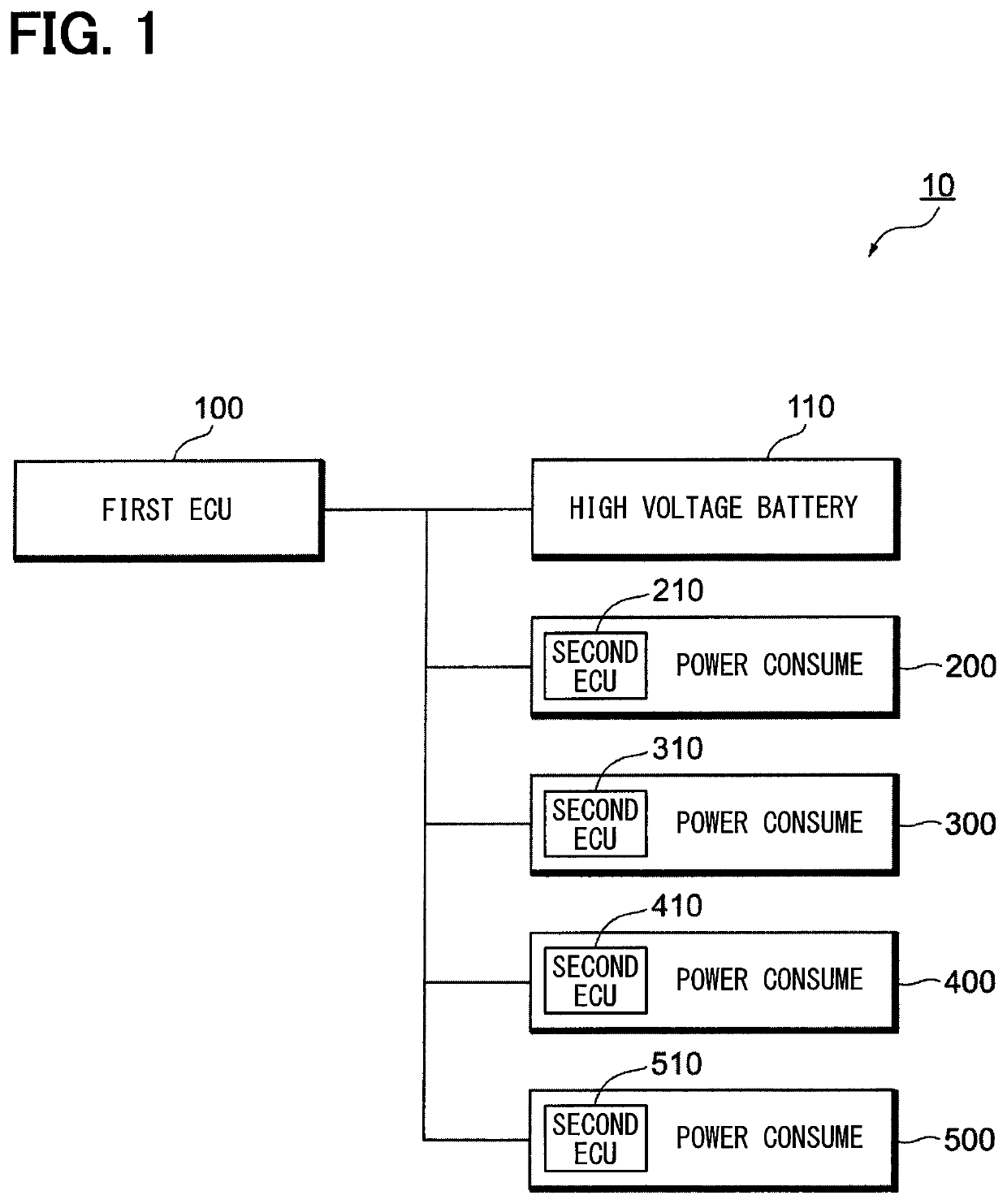
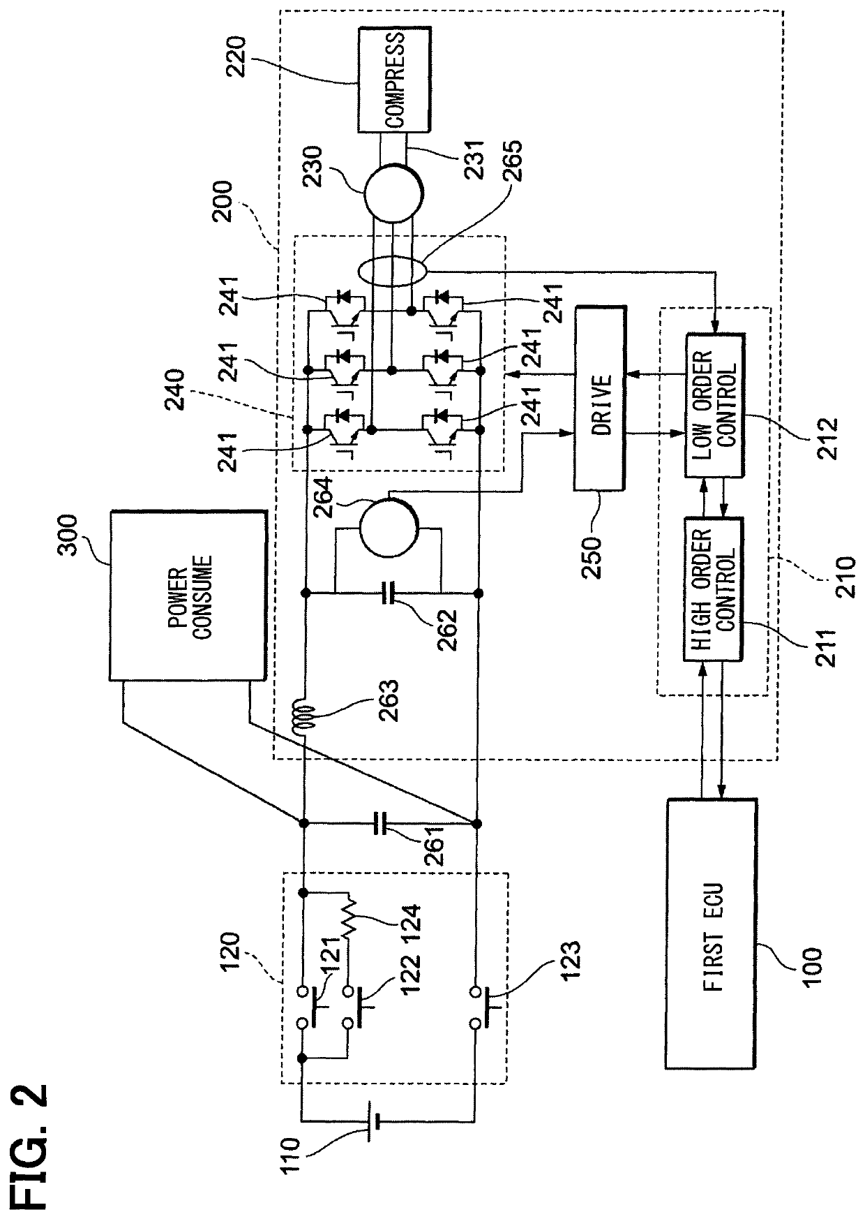
[0030]The following will explain a configuration of a power control system 10 according to a first embodiment of the present disclosure with reference to FIGS. 1 to 3. The power control system 10 is configured to perform the electric power supply to each of a plurality of power consumption devices 200, 300, 400, and 500 installed in a vehicle (unshown).

[0031]As schematically illustrated in FIG. 1, the electric vehicle is mounted with a first ECU 100, a high voltage battery 110, and four power consumption devices 200, 300, 400, and 500.

[0032]The high voltage battery 110 is a storage battery for providing the electric power to a dynamo-electric machine (unshown) included in the electric vehicle. In addition, the high voltage battery 110 provides also the electric power for operation to each of the power consumption devices 200, 300, 400, and 500. The maximum of the electric power, i.e., the allocation of the available electric power (represented as “electric power allocation,” hereina...

second embodiment

[0096]A second embodiment of the present disclosure will be explained with reference to FIG. 9. In the present embodiment, a process that determines a specific mode of the electric power restriction A (or the electric power restriction B) is different from the first embodiment. The process performed by the second embodiment replaces a series of processing as in FIG. 8 with a series of processing as in FIG. 9.

[0097]A series of processing as in FIG. 9 are added with the processing of S32, S33, and S34 to FIG. 8. Of the processing in FIG. 9, the processing identical to that in FIG. 8 such as S21 is assigned with the identical sign. The following will explain only S32, S33, and S34.

[0098]In S32 performed after S21, the mode of the electric power restriction is determined; namely, it is determined whether an instruction indicating a specific mode is included in the restriction mode flag. When any instruction is not included in the restriction mode flag, the sequence proceeds to S22 and t...

third embodiment

[0103]A third embodiment of the present disclosure will be explained with reference to FIG. 10. Now, (A) of FIG. 10 indicates the time change of the electric power allocation transmitted to the power consumption device 200 from the first ECU 100. In contrast, (B) of FIG. 10 illustrates the change of the consumed electric power in the power consumption device 200.

[0104]The electric power allocation is transmitted from the first ECU 100 to the second ECU 210 each a predetermined communication period elapses. This makes it difficult to decrease the electric power allocation with a predetermined slope as in (A) of FIG. 5, for instance. Thus, in the present embodiment, the first ECU 100 transmits the electric power allocation with the mode of instant restriction and instant release as in (A) of FIG. 10; the second ECU 210 performs the electric power restriction or the release of the electric power restriction with a gentle slope. See, in (B) of FIG. 10, a period from the time t10 to the ...


PUM


Abstract

A power control system supplies electric power to a plurality of power consumption devices which are provided to an electric vehicle. This system includes: a high voltage battery which is an electric power supply source; a plurality of device controllers which are provided to the respective power consumption devices and which control operations of the respective power consumption devices; and an overall controller which overall controls the plurality of device controllers. At least one of the device controllers performs an electric power restriction that restricts a consumed electric power in a corresponding power consumption device so as to allow the consumed electric power in the corresponding power consumption device to fall within an electric power allocated by the overall controller while simultaneously maintaining an operation of the corresponding power consumption device stably.

Description

CROSS REFERENCE TO RELATED APPLICATIONS[0001]This application is a U.S. National Phase Application under 35 U.S.C. 371 of International Application No. PCT / JP2016 / 001817 filed on Mar. 29, 2016 and published in Japanese as WO 2016 / 189787 A1 on Dec. 1, 2016. This application is based on and claims the benefit of priority from Japanese Patent Application No. 2015-104194 filed on May 22, 2015. The entire disclosures of all of the above applications are incorporated herein by reference.TECHNICAL FIELD[0002]The present disclosure relates to a power control system that performs electric power supply to a plurality of power consumption devices installed in an electric vehicle.BACKGROUND ART[0003]There is recently becoming popular an electric vehicle that runs with an electric power stored in a high voltage battery. The electric vehicle drives a dynamo-electric machine with the electric power stored in the high voltage battery, and runs with the driving force of the dynamo-electric machine. ...

Claims


Application Information

Patent Timeline
Patent Type & Authority Patents(United States)
IPC IPC(8): B60L1/00B60L1/02H02J1/08H02J1/14H02J13/00B60L58/12B60L1/08H02P27/06
CPCB60L58/12B60L1/02H02J1/14H02J13/00B60L1/08B60L1/003B60L1/00H02J1/08H02P27/06H02J2310/48Y02T10/70H02J13/00036
Inventor SAKAI, KOJISUMI, TOMOYUKI
Owner DENSO CORP
Why Eureka
Try Eureka