
Method for communication network performance analysis

a communication network and performance analysis technology, applied in the field of communication network performance analysis, can solve the problems of difficult acquisition of downlink direction information for optimization purposes, inability to quantitatively verify the success of the optimization, and high cost of data collection and time-consuming, so as to achieve the effect of higher resolution

Active Publication Date: 2009-05-19
NOKIA TECH OY
View PDF11 Cites 18 Cited by
  • Summary
  • Abstract
  • Description
  • Claims
  • Application Information

AI Technical Summary

Benefits of technology

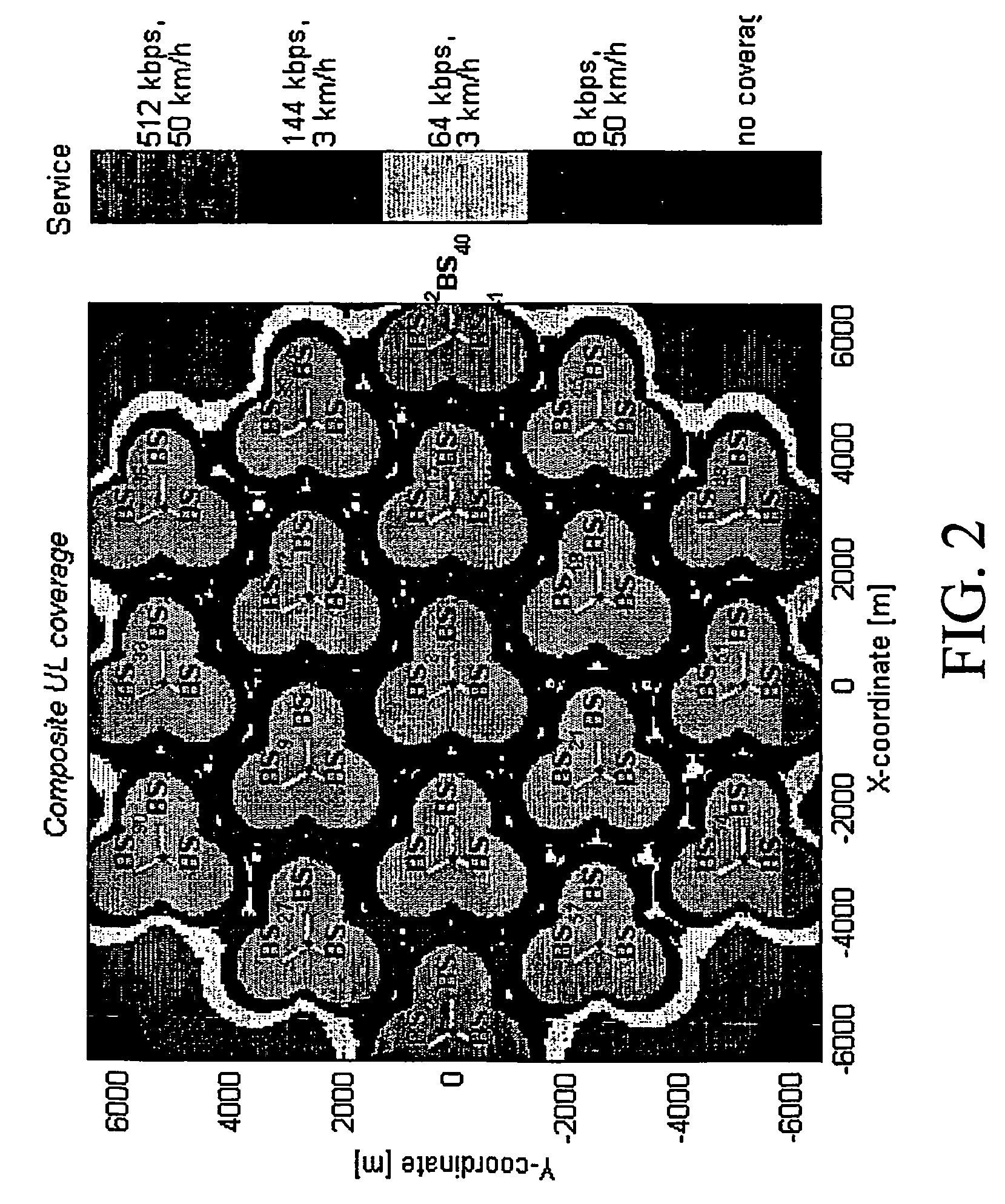
This approach reduces costs, enhances data accuracy, and allows for permanent tracing of terminal positions, enabling efficient network planning and optimization by providing comprehensive service coverage and throughput statistics, improving network performance analysis and visualization.

Problems solved by technology

In order to effectively perform such a network planning, however, a most properly executed network performance analysis is required, since otherwise network planning would result in a mere “trial and error” process which is cumbersome and rather time consuming, and the success of which is doubtful and can not be verified quantitatively.
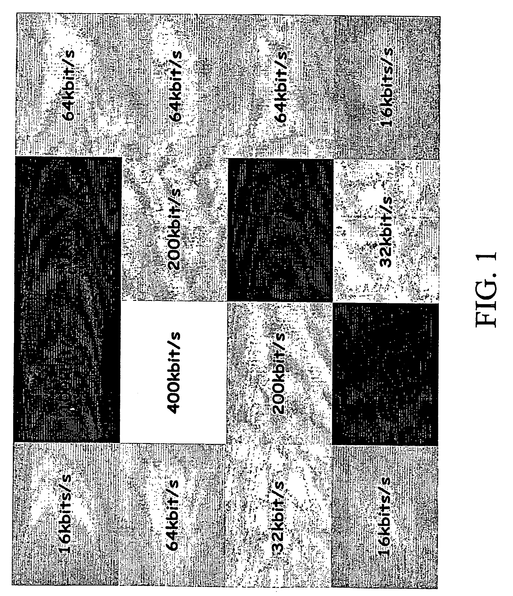
The main issue is that the definition of service is related to a set of at least one attribute and these attributes define the dimensions of the “information matrix” to be used.
Traditionally the downlink direction information for optimization purposes has been very difficult to acquire.
The only way to collect coverage related data has been with drive tests with field tool and this requires relatively lot manpower which makes data collection quite expensive and also time consuming.
Furthermore, the field tool data has not been transferred to Network Management System (NMS) for further analysis and thus the coverage information is based either on planning tool (very inaccurate) or statistical “snapshots” based on drive tests in the network (these are in addition only related to a limited area of the network dependent on the number of drive tests conducted simultaneously).

Method used


Image

  • Method for communication network performance analysis
  • Method for communication network performance analysis
  • Method for communication network performance analysis

Examples


Embodiment Construction

[0043]Now, the present invention will be described with reference to the attached drawings.

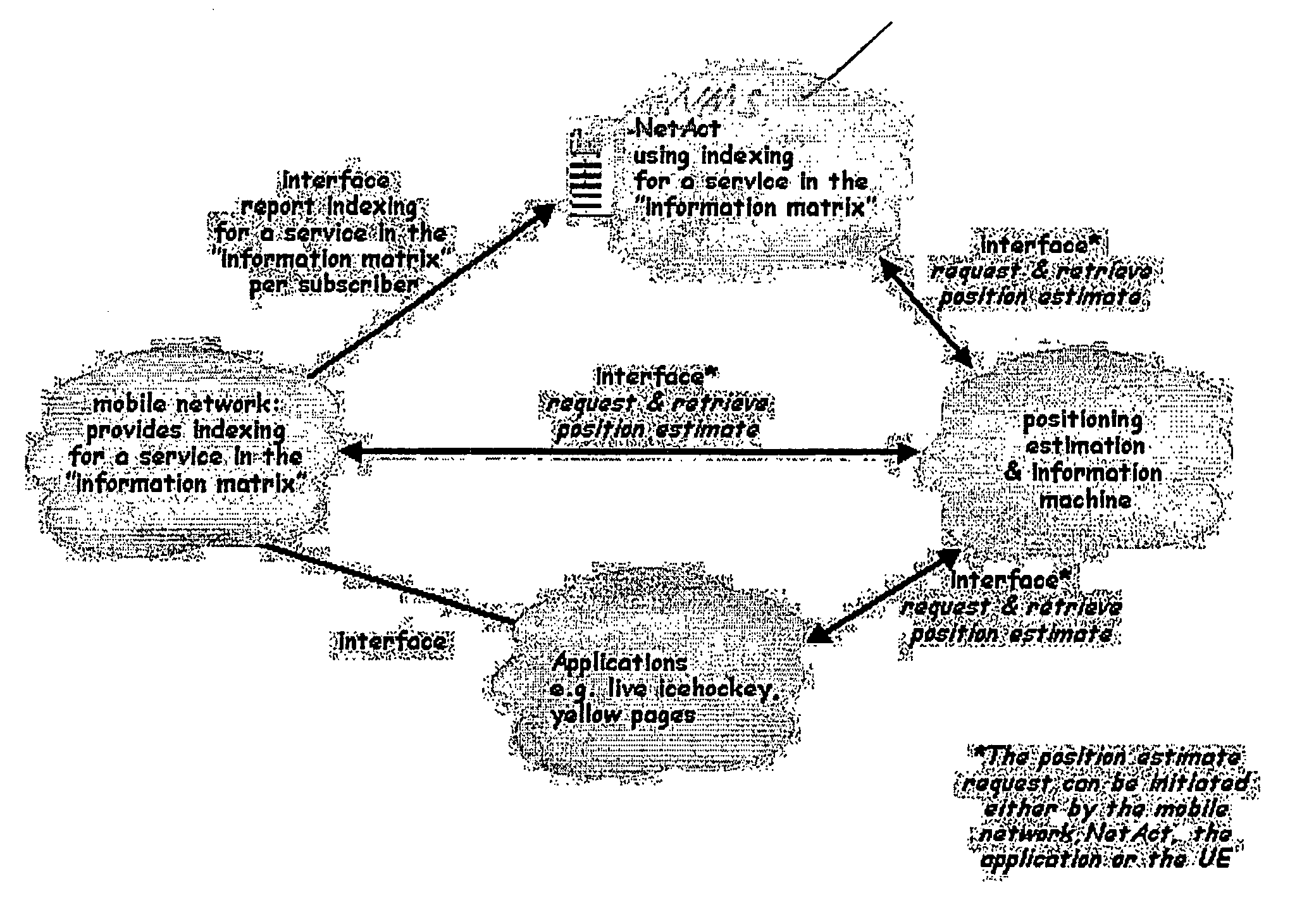
[0044]FIG. 3 shows a block circuit representation of entities involved in carrying out the present method and some signaling there between in connection with an embodiment of the present invention. As shown in FIG. 3, when implementing the present invention there are involved the mobile network including all network entities, applications run on and / or by means of the mobile network such as live icehockey transmissions, yellow pages or email. For illustration purposes a position estimation and information machine (e.g. a mobile location center such as a GMLC (Gateway Mobile Location Center) or SMLC (Serving Mobile Location Center)) and a network management or corresponding system entity denoted as NMS are shown separately, even though they may be considered as forming part of the mobile network as such.

[0045]Between these entities, requests and resulting information can be transmitted via inte...


PUM


Abstract

The present invention relates to a method for communication network parameter setting comprising the steps of a) acquiring and storing information related to a1) service requests issued by terminals attached to the network, a2) positions of the terminals, and a3) establishment of the requested service for the terminals, b) matching, based on the position information, the information to a grid of unit areas, the grid of unit areas representing a geographical region in which the network is operated, c) processing the information per unit area, d) outputting the processed information and e) modifying communication network operating parameters based on the outputted processed information.

Description

FIELD OF THE INVENTION[0001]The present invention relates to a method for communication network performance analysis.BACKGROUND OF THE INVENTION[0002]Recently, communication networks have widely spread and are used by a continuously increasing number of subscribers. In order to cope with the increasing number of subscribers and correspondingly the increasing number of terminals of said subscribers which are potentially attached to the network for communication purposes, communication networks have to be most carefully planned in order that the network can be operated smoothly while meeting all requirements of the subscribers.[0003]It is to be noted that the present invention is not limited to a specific type of communication network. It may be for example a wireless communication network such as the UMTS network or any other communication network. Also, network planning is to be understood as a process of setting network operating parameters such as transmit power, antenna character...

Claims


Application Information

Patent Timeline
Patent Type & Authority Patents(United States)
IPC IPC(8): H04J1/16H04W24/00
CPCH04W24/00
Inventor LAIHO, JAANASTEFFENS, WOLFGANG
Owner NOKIA TECH OY
Learn More