Entangled quantum communications and quantum imaging

a quantum communication and quantum imaging technology, applied in the field of communications apparatus and methods, can solve problems such as power, cost, weight and robustness of operation

Inactive Publication Date: 2009-05-19
ARMY US SEC THE THE
View PDF17 Cites 47 Cited by
  • Summary
  • Abstract
  • Description
  • Claims
  • Application Information

AI Technical Summary

Problems solved by technology

One challenge common to QKD and other communication methods are the speed of the sender's laser modulation, speed of receiver's detec

Method used


Image

  • Entangled quantum communications and quantum imaging
  • Entangled quantum communications and quantum imaging
  • Entangled quantum communications and quantum imaging

Examples


Embodiment Construction

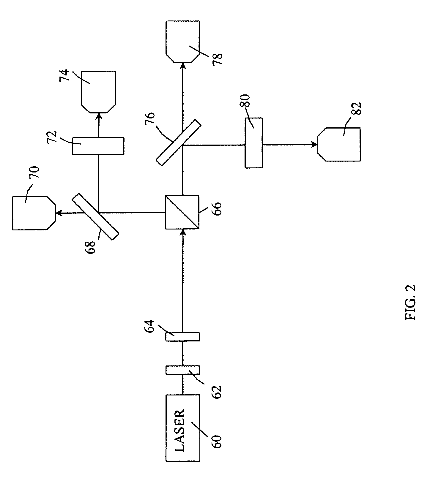
[0013]A number of optical systems are described below. Orientations of crystals (and of polarizations) are given relative to horizontal in the laboratory frame. However, other equivalent configurations will be apparent to those skilled in the arts.

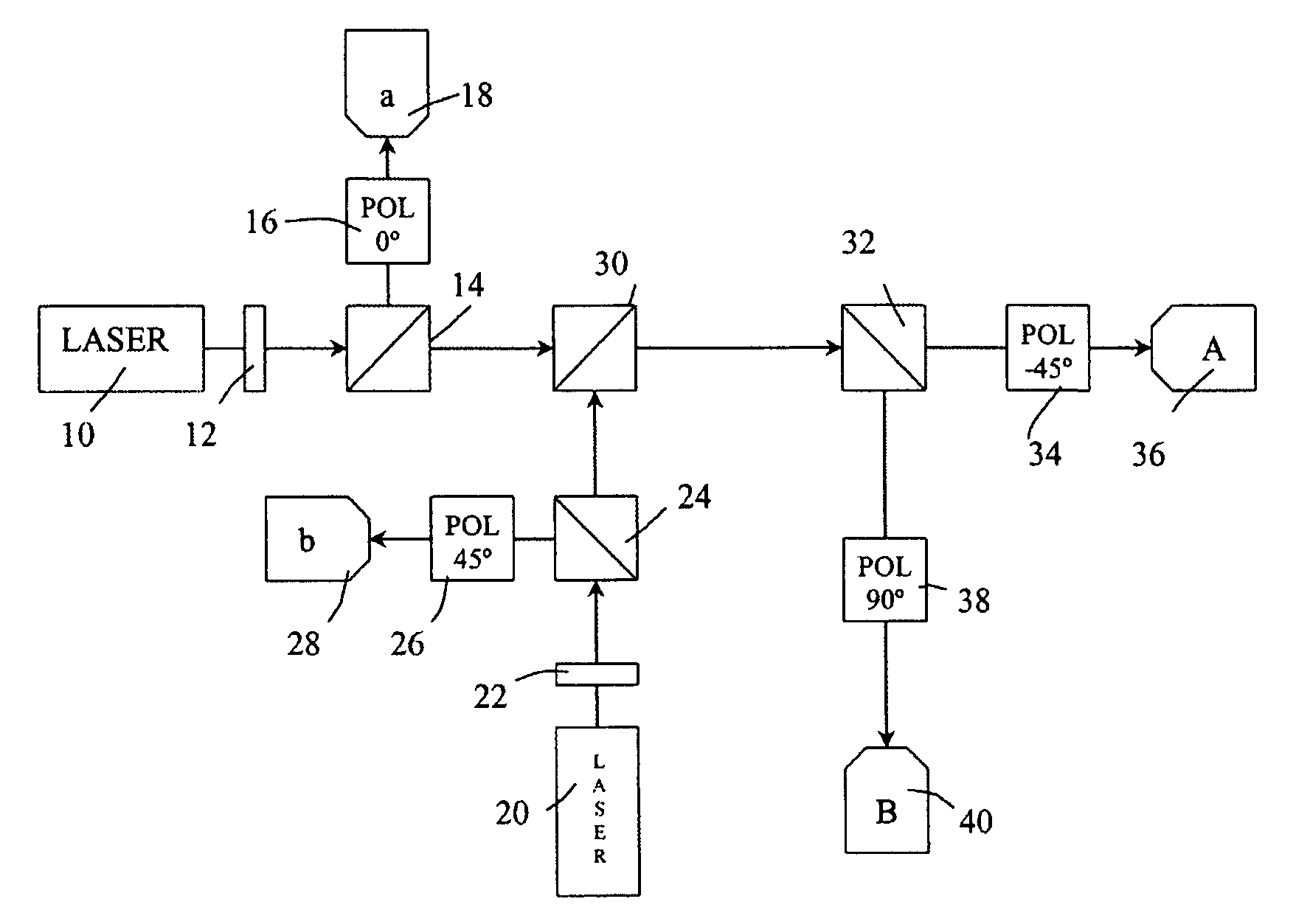
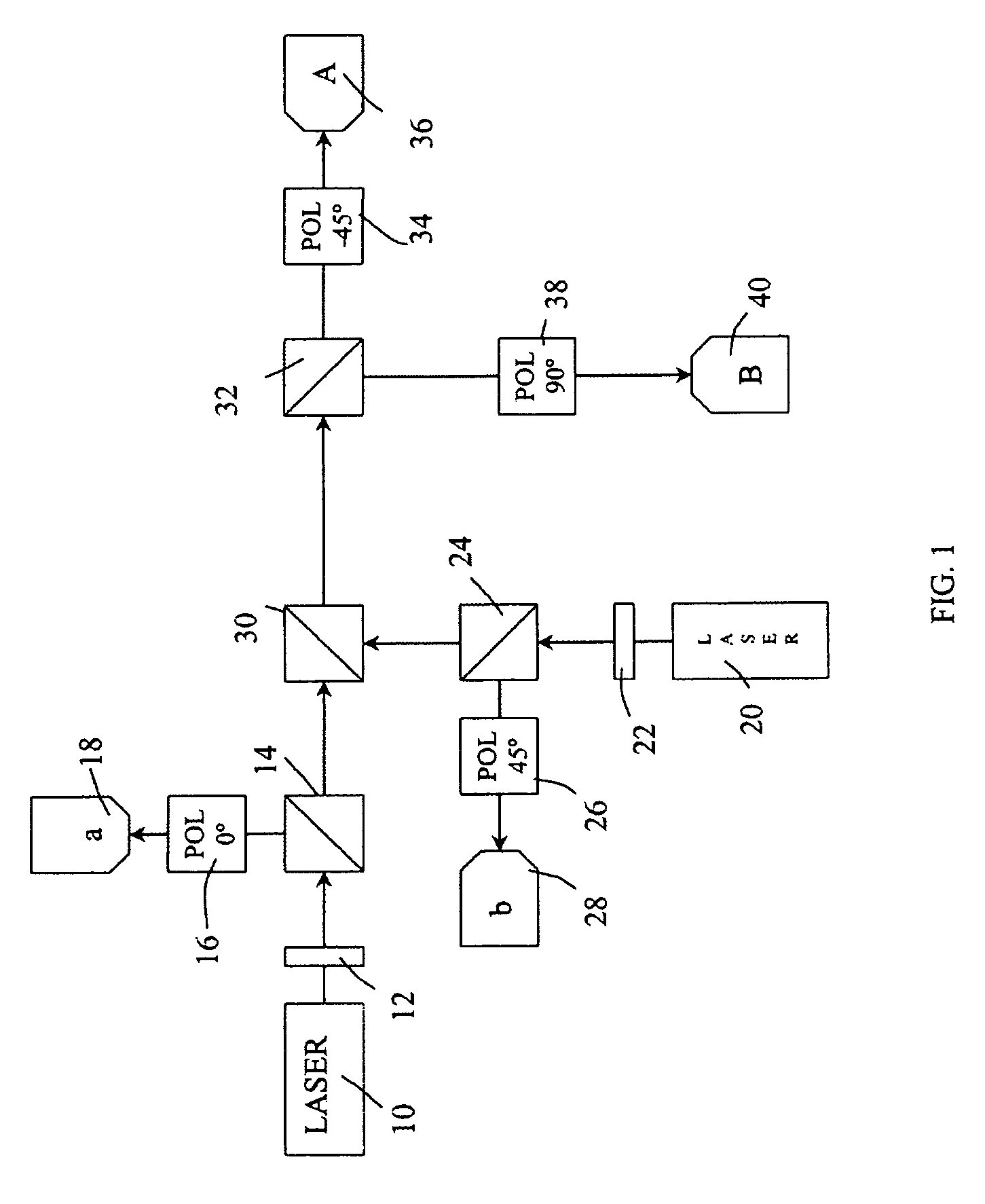
Heralded Stochastic Quantum Key Distribution (HSQKD) System

[0014]FIG. 1 is a schematic of a HSQKD system, which includes a sending system and a receiving system. The sending system comprises a first laser 10, a first nonlinear crystal 12, a first beam-splitter 14, a first polarizer 16, a first detector 18, a second laser 20, a second nonlinear crystal 22, a second beam-splitter 24, a second polarizer 26, a second detector 28, and a beam recombiner 30. The receiving system (receiver) includes receiver beam-splitter 32, a first receiver polarizer 34, a first receiver detector 36, a second receiver polarizer 38, and a second receiver detector 40. The lines joining optical components show beam paths, the arrows indicate direction of the beams....


PUM


Abstract

An apparatus for generating a shared quantum key between a sender and a receiver comprises a sending apparatus which generates entangled photon pairs, and a receiving apparatus. A shared quantum key can be generated using temporal coincidences between photon detection events. For example, coincidences may be determined between sender and receiver photon detection events using detection data shared through a non-secure communications link between the sender and receiver. The quantum key can be used in encrypted communications. Similar apparatus and methods can be used for quantum imaging.

Description

REFERENCE TO RELATED APPLICATION[0001]This application claims priority to provisional application U.S. Ser. No. 60 / 493,107, filed Aug. 6, 2003, the entire contents of which are incorporated herein by reference.GOVERNMENT INTEREST[0002]The invention described herein may be manufactured, used, and licensed by or for the United States Government.FIELD OF THE INVENTION[0003]The present invention relates to apparatus and methods for communications, in particular to encrypted communications.BACKGROUND OF THE INVENTION[0004]Quantum key distribution (QKD) endeavors to generate and distribute cryptographic keys using quantum physics in order to provide a higher level of security in communications than can be accomplished using classical means. There are significant challenges that must be overcome to accomplish this goal in practice.[0005]One challenge common to QKD and other communication methods are the speed of the sender's laser modulation, speed of receiver's detectors, and reasonable a...

Claims


Application Information

Patent Timeline
IPC IPC(8): H04L9/00H04L9/12
CPCH04L9/0858
Inventor MEYERS, RONALD E.DEACON, KEITH S.ROSEN, DAVID L.
Owner ARMY US SEC THE THE
Why Eureka
Try Eureka