Optical laser guidance system apparatus and method

a laser guidance and optical technology, applied in the direction of mechanical control devices, distance measurement, programme control, etc., can solve the problems of slow development of this vision, many difficulties that have yet to be overcome, and the development of free-roaming robotic machines capable of navigating their way over a variety of different surfaces, etc., to achieve a high degree of positional accuracy

Active Publication Date: 2009-05-19
THE BOEING CO
View PDF8 Cites 17 Cited by
  • Summary
  • Abstract
  • Description
  • Claims
  • Application Information

AI Technical Summary

Benefits of technology

[0006]The foregoing needs are met, to a great extent, by the present invention, wherein in one aspect an apparatus and method are provided that in some embodiments provide laser-based navigational guidance and control of a vehicle, such as a robot, with a high degree of positional accuracy, while limiting the quantity and complexity of real-time calculations necessary to determine and correct the position of the vehicle, in two-dimensions as well as in three-dimensions, by tracking a laser beam projected from a remote source.

Problems solved by technology

Although scientists anticipated years ago that automated machines, or robots, could be designed to perform myriad tasks in the place of humans, and the general expectation that robots one day should perform the majority of mundane physical tasks has become ubiquitous, the realization of this vision has been slow to develop.
Even with the prominence of the modern microprocessor, many difficulties have yet to be overcome before robotic machines will be capable of performing common tasks easily performed by humans.
While stationary robots with multi-jointed appendages may be programmed to execute specific movements within a limited area, or such robots may be transported about an extended area by a gantry, the development of free-roaming robotic machines capable of navigating their way over a variety of different surfaces has proven more difficult.
A number of navigation schemes for such vehicles have met with limited success, based on technologies such as gyroscopes, magnetic sensors, wheel encoders, radio transponder sensors, the Global Positioning System (GPS), or laser reflectors.
Unfortunately, each of these systems fails to provide a cost effective solution with the required accuracy and response time.
For example, some existing systems present response-time difficulties due to the complexity of the required real-time calculations.
These difficulties are compounded when three-dimensional, as opposed to two-dimensional, navigation and control is contemplated.
Other systems do not provide sufficient accuracy for applications that require increased precision, such as certain manufacturing processes.
Furthermore, existing positioning and navigation systems may be cost prohibitive.

Method used


Image

  • Optical laser guidance system apparatus and method
  • Optical laser guidance system apparatus and method
  • Optical laser guidance system apparatus and method

Examples


Embodiment Construction

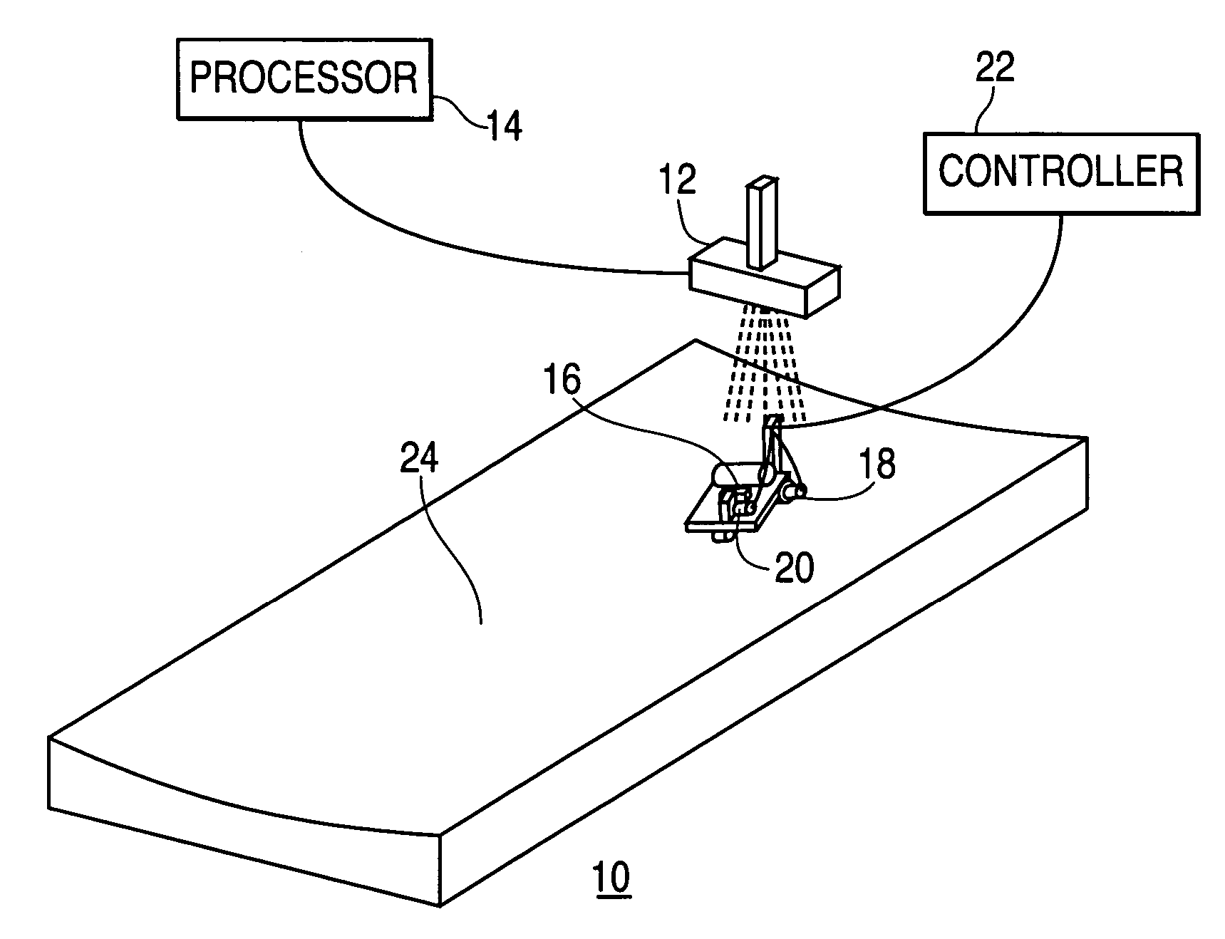
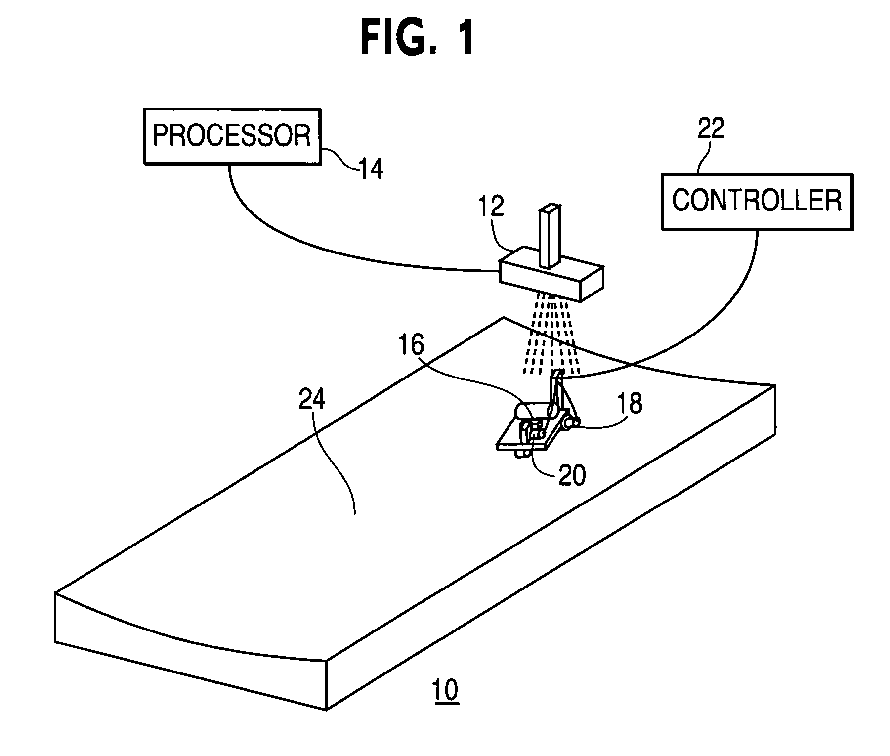
[0019]The invention will now be described with reference to the drawing figures, in which like reference numerals refer to like parts throughout. A preferred embodiment in accordance with the present invention, illustrated in FIG. 1, provides an optical laser guidance system 10 that includes a laser source 12 and an associated processor 14, a laser sensor 16 mounted on a vehicle, two drive actuators—a drive wheel actuator 18 and a steering actuator 20—attached to the vehicle, and an associated controller 22.

[0020]In this embodiment, a laser beam is projected in a manner so as to delineate a guidepath corresponding to a contoured surface 24, and the laser sensor 16 detects the location of the laser beam, which may be continuous or pulsed. As used herein, a guidepath represents a projected curvilinear path through space that provides navigational guidance for a vehicle. A guidepath may lie on or correspond to a two-dimensional or three dimensional surface, or may be independent of any...


PUM

PropertyMeasurementUnit
photosensitiveaaaaaaaaaa
frequencyaaaaaaaaaa
relative velocityaaaaaaaaaa

Abstract

An optical laser guidance system includes a laser sensor, a controller and a plurality of actuators. The laser sensor detects a projected laser beam and sends an electrical signal representative of the position of the laser beam to the controller. The controller interprets the representative signal and uses the position of the laser beam relative to a predetermined reference position to generate a control signal to control an actuator in order to control the direction of travel of a vehicle or robot with respect to a predetermined guidepath. The laser sensor may also receive additional control messages that result in the controller generating additional control signals to control additional actuators in order to perform additional functions. The optical laser guidance system may also include a laser projection system capable of projecting a two- or three-dimensional guidepath and additional control messages.

Description

FIELD OF THE INVENTION[0001]The present invention relates generally to vehicle guidance systems. More particularly, the present invention relates to optical laser-based navigation and control systems for robotic manufacturing devices.BACKGROUND OF THE INVENTION[0002]Although scientists anticipated years ago that automated machines, or robots, could be designed to perform myriad tasks in the place of humans, and the general expectation that robots one day should perform the majority of mundane physical tasks has become ubiquitous, the realization of this vision has been slow to develop. Even with the prominence of the modern microprocessor, many difficulties have yet to be overcome before robotic machines will be capable of performing common tasks easily performed by humans. Nevertheless, significant advancements have been made in this area of technology, particularly with regards to application-specific robotic machines developed to perform specialized tasks in mass-production or hi...

Claims


Application Information

Patent Timeline
Patent Type & Authority Patents(United States)
IPC IPC(8): G05D1/00
CPCG05B19/4207G05D1/0236G05B2219/36439G05D2201/0202G05D1/02
Inventor LEDET, ROGER J.YESTRAU, JOHN E.
Owner THE BOEING CO
Why Eureka
Try Eureka