
System, method, and computer program product for sending remote device configuration information to a monitor using e-mail

a technology of remote device configuration and monitor, applied in the field of system, method and computer program products for monitoring networked devices, can solve problems such as increasing the complexity of providing such a capability

Inactive Publication Date: 2009-05-19
RICOH KK
View PDF44 Cites 39 Cited by
  • Summary
  • Abstract
  • Description
  • Claims
  • Application Information

AI Technical Summary

Benefits of technology

[0010]One advantage of the present invention is that devices from multiple networks may be monitored from a central location without the need for additional processing to resolve device address ambiguities. Another advantage of the present invention is the devices connected to any particular network may continue to be monitored using an IP-based protocol, such as SNMP. Moreover, since address ambiguities are resolved by, for example, a MAC address, prior to sending the monitoring information to a central monitor, there is no requirement that the devices being monitored have globally-unique IP addresses, thereby allowing the present invention to be used in networks that include, for example, NATs.
[0011]Consistent with the title of this section, the above summary is not intended to be an exhaustive discussion of all the features or embodiments of the present invention. A more complete, although not necessarily exhaustive, description of the features and embodiments of the invention is found in the section entitled “DESCRIPTION OF THE PREFERRED EMBODIMENTS.”

Problems solved by technology

However, an IP address is not necessarily a globally-unique identifier for a particular device.
These addressing complexities present difficulties to applications that wish to maintain information on the individual devices of a plurality of networks that may or may not share IP addresses.
However, device address ambiguities increases the complexity of providing such a capability.

Method used


Image

  • System, method, and computer program product for sending remote device configuration information to a monitor using e-mail
  • System, method, and computer program product for sending remote device configuration information to a monitor using e-mail
  • System, method, and computer program product for sending remote device configuration information to a monitor using e-mail

Examples


Embodiment Construction

.”

BRIEF DESCRIPTION OF THE DRAWINGS

[0012]A more complete appreciation of the invention and many of the attendant advantages thereof will be readily obtained as the same becomes better understood by reference to the following detailed description when considered in connection with the accompanying drawings, wherein:

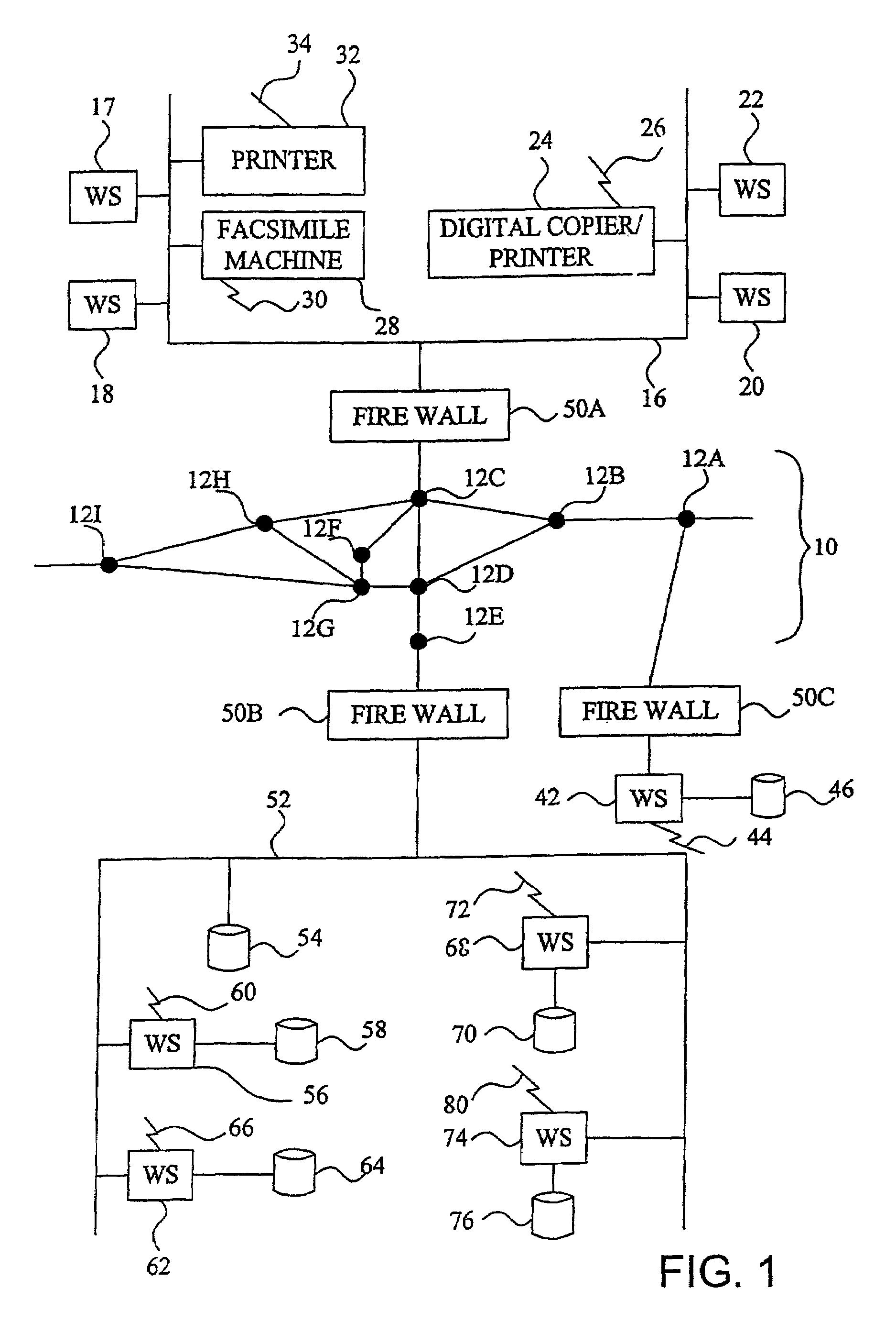
[0013]FIG. 1 illustrates three networked business office devices connected to a network of computers and databases through the Internet;

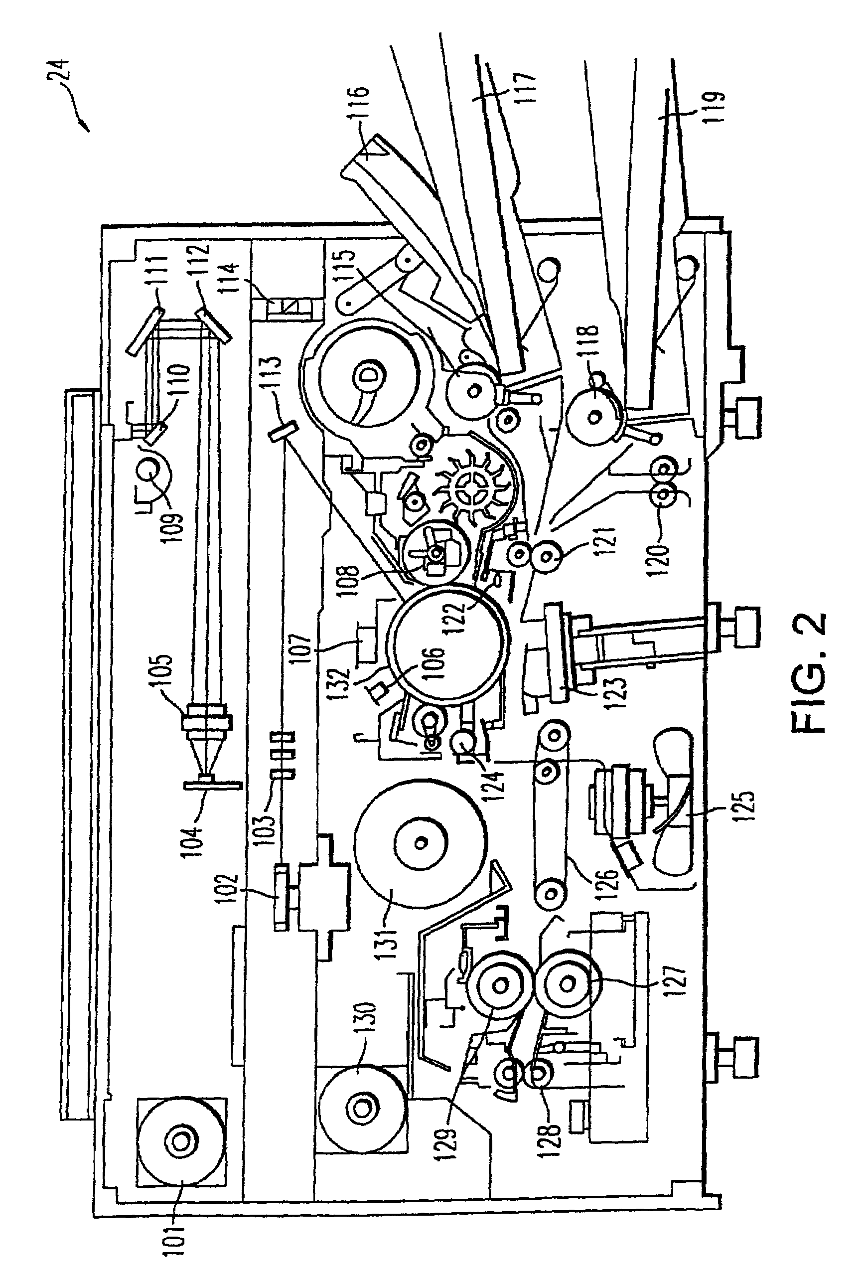
[0014]FIG. 2 illustrates the components of a digital image forming apparatus;

[0015]FIG. 3 illustrates the electronic components of the digital image forming apparatus illustrated in FIG. 2;

[0016]FIG. 4 illustrates details of a multi-port communication interface illustrated in FIG. 3;

[0017]FIG. 5 illustrates an alternative system configuration in which business office devices are either connected directly to the network or connected to a computer which is connected to the network;

[0018]FIG. 6A is a block diagram illustrating a flow of infor...


PUM


Abstract

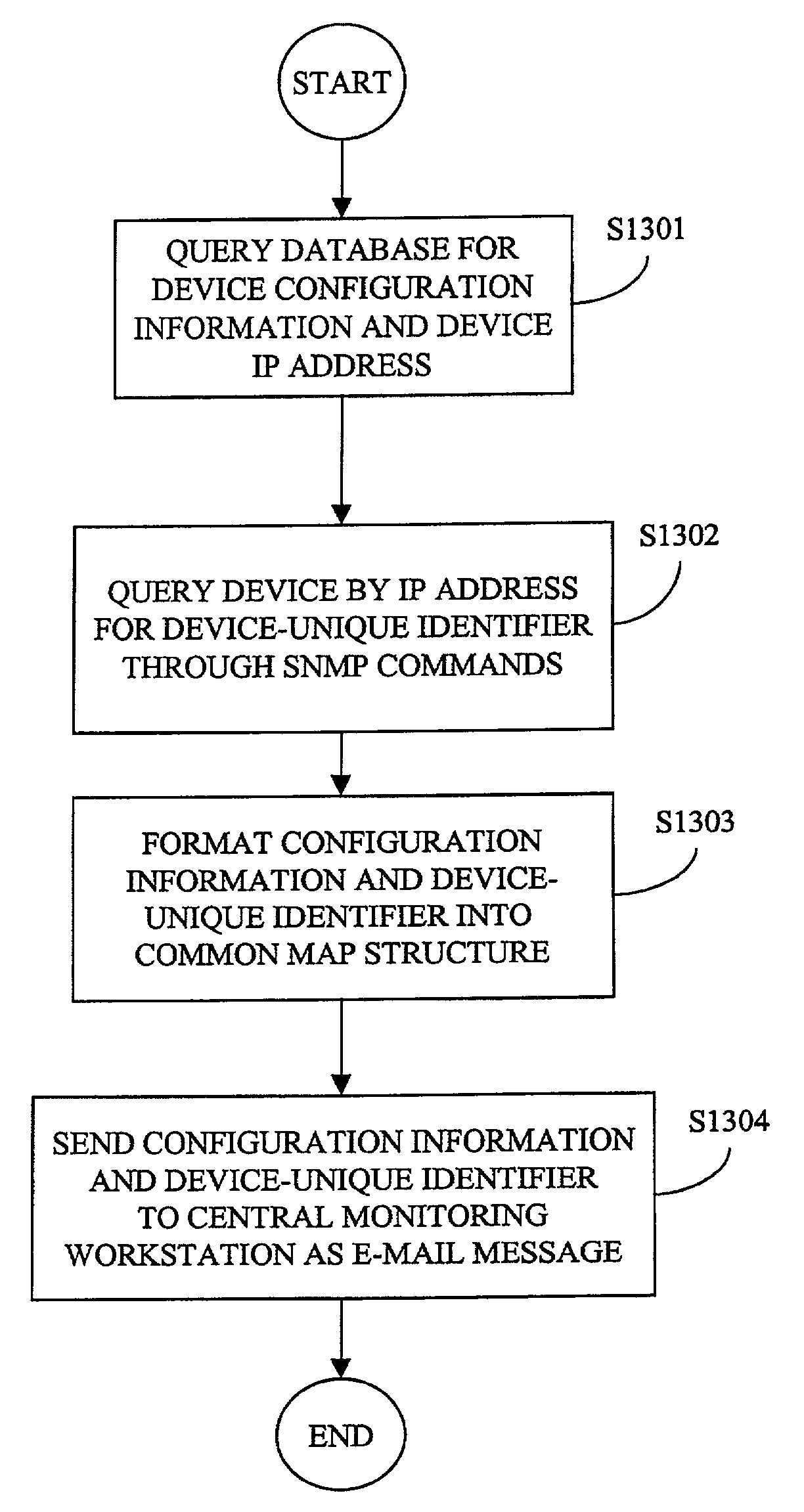
In a monitoring system for networked devices, a system, method, and computer program product for obtaining a globally-unique identifier for a network device, and sending the same to a central monitor responsible for monitoring devices on multiple networks. A remote monitoring workstation monitors devices connected to a network using IP-based SNMP commands and stores the device monitoring information in a database. The remote monitoring workstation queries the database to obtain an IP address and the collected monitoring information for a device, uses the IP address to request a globally-unique identifier (e.g., a MAC address) from a device using SNMP commands, then sends the monitoring information including the globally-unique device identifier to a central monitoring workstation via an e-mail message.

Description

CROSS-REFERENCE TO RELATED APPLICATIONS[0001]The present application is related to U.S. patent application Ser. No. 09 / 190,460, filed Nov. 13, 1998, entitled “Method and System for Translating Documents Using Different Translation Resources for Different Portions of the Documents,” which is a continuation of U.S. patent application Ser. No. 08 / 654,207, filed May 28, 1996, entitled “Method and System for Translating Documents Using Different Translation Resources for Different Portions of the Documents,” now U.S. Pat. No. 5,848,386; U.S. patent application Ser. No. 08 / 997,705, filed Dec. 23, 1997, entitled “Object-oriented System and Computer Program Product for Mapping Structured Information to Different Structured Information,” now U.S. Pat. No. 6,085,196; U.S. patent application Ser. No. 08 / 997,705, filed Dec. 23, 1997, entitled “Method and Apparatus for Providing a Graphical User Interface for Creating and Editing a Mapping of a First Structural Description to a Second Structural...

Claims


Application Information

Patent Timeline
IPC IPC(8): G06F15/16G06F15/173G06F15/00G06F3/12G06K1/00H04L12/24H04L29/12
CPCH04L12/58H04L29/12518H04L41/0213H04L41/026H04L41/0843H04L41/0856H04L61/2571H04L29/12028H04L61/103H04L51/00
Inventor MOTOYAMA, TETSUROFONG, AVERY
Owner RICOH KK
Learn More