
Multi-mode amplitude modulator control method

a multi-mode amplitude modulator and control method technology, applied in the field of radio devices, can solve the problems of low efficiency and fast linear part 200 b>

Active Publication Date: 2009-05-26
NOKIA TECH OY
View PDF2 Cites 10 Cited by
  • Summary
  • Abstract
  • Description
  • Claims
  • Application Information

AI Technical Summary

Benefits of technology

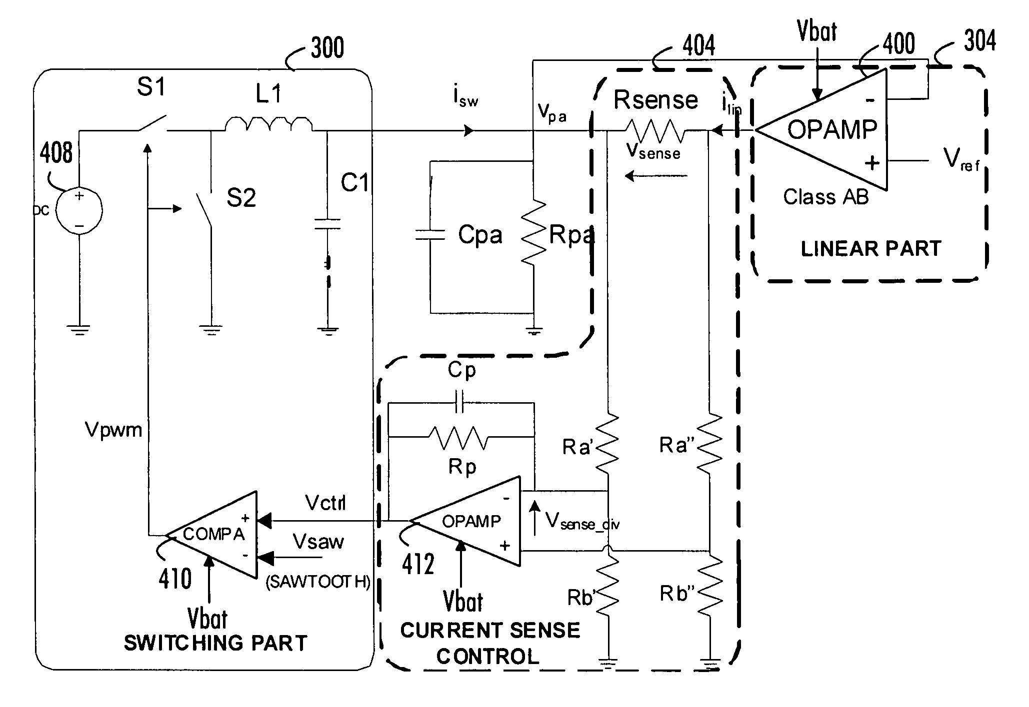
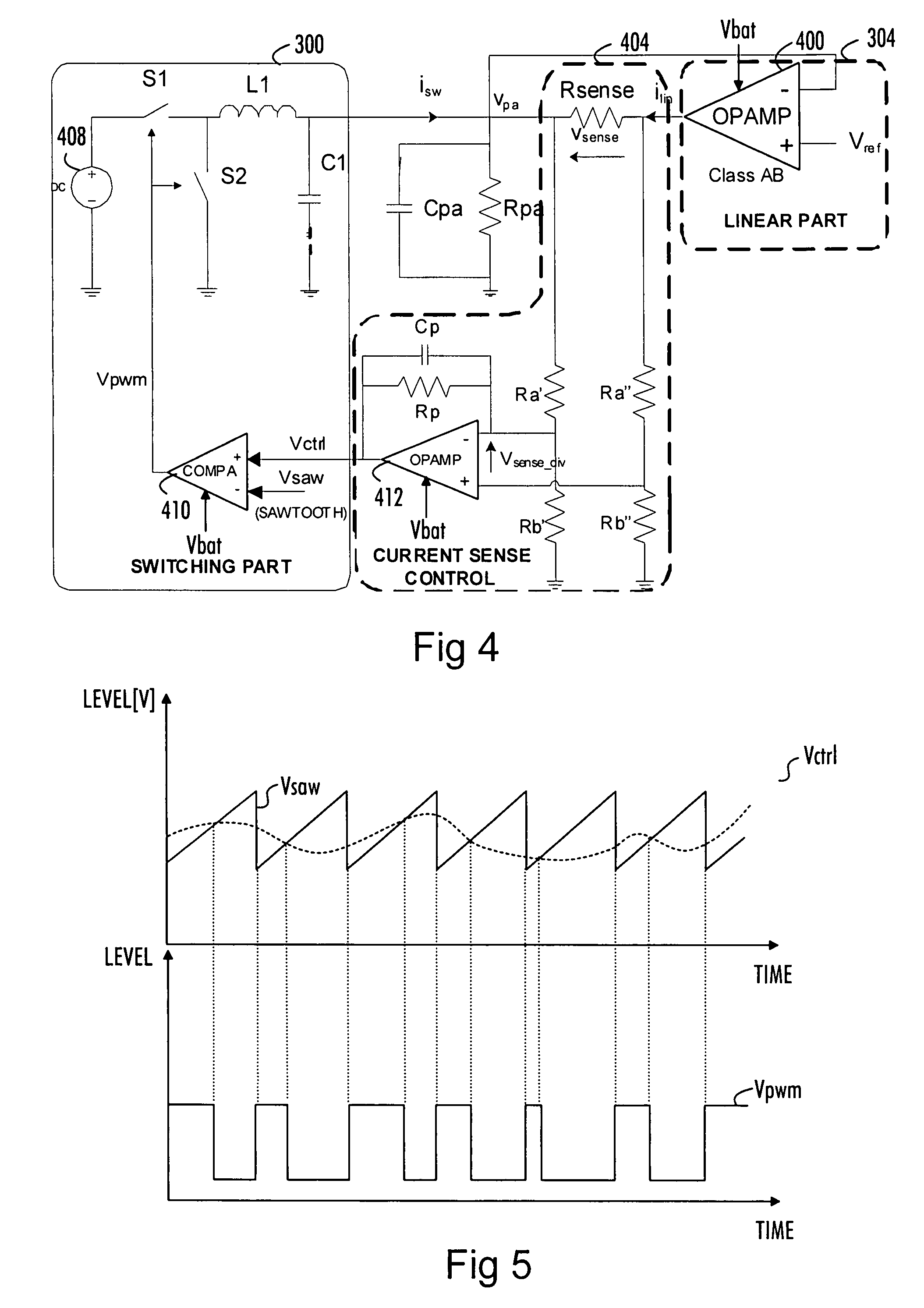
[0011]According to an aspect of the invention, there is provided a parallel-hybrid amplitude modulator apparatus, comprising an interface to receive an input signal, a linear part configured to track frequency components of the input signal above a determined threshold frequency, a switching part arranged in parallel with the linear part and configured to track frequency components of the input signal below the determined threshold frequency, and a current sensing and controlling part configured to determine the level of a direct current component at an output of the linear part and control the switching part to produce an output signal compensating for the direct current component at the output of the linear part to decrease the absolute level of the direct current at the output of the linear part.
[0014]According to another aspect of the invention, there is provided a parallel-hybrid amplitude modulator apparatus, comprising means for receiving an input signal, linear means for tracking frequency components of the input signal above a determined threshold frequency, switching means arranged in parallel with the linear means and configured to track frequency components of the input signal below the determined threshold frequency, current sensing and controlling means for determining the level of a direct current component at an output of the linear means and control the switching means to produce an output signal compensating for the direct current component at the output of the linear part to decrease the absolute level of the direct current at the output of the linear means.
[0015]According to another aspect of the invention, there is provided a parallel-hybrid amplitude modulator apparatus, comprising an interface to receive an input signal, a linear part configured to track frequency components of the input signal above a determined threshold frequency, a switching part arranged in parallel with the linear part and configured to track frequency components of the input signal below the determined threshold frequency, a direct current voltage source providing at least the linear part with a direct current supply voltage, and a scaling unit configured to scale the direct current supply voltage to a level higher than a desired maximum output voltage of the parallel hybrid amplitude modulator to ensure the operation of the linear part with good efficiency.
[0016]According to another aspect of the invention, there is provided a parallel-hybrid amplitude modulator apparatus, comprising means for receiving an input signal, linear means for tracking frequency components of the input signal above a determined threshold frequency, switching means arranged in parallel with the linear means and configured to track frequency components of the input signal below the determined threshold frequency, direct current voltage supply means for providing at least the linear part with a direct current supply voltage, and scaling means for scaling the direct current supply voltage to a level higher than a desired maximum output voltage of the parallel hybrid amplitude modulator to ensure the operation of the linear means with good efficiency.

Problems solved by technology

The linear part 200 is fast, but has a low efficiency.
A problem associated to the parallel-hybrid topology is how to ensure the correct current sharing between the switching part and the linear part.
The problem is similar regardless of whether a radio transmitter comprising the parallel hybrid amplitude modulator utilizes an envelope tracking power management device or a polar transmitter structure.

Method used


Image

  • Multi-mode amplitude modulator control method
  • Multi-mode amplitude modulator control method
  • Multi-mode amplitude modulator control method

Examples


Embodiment Construction

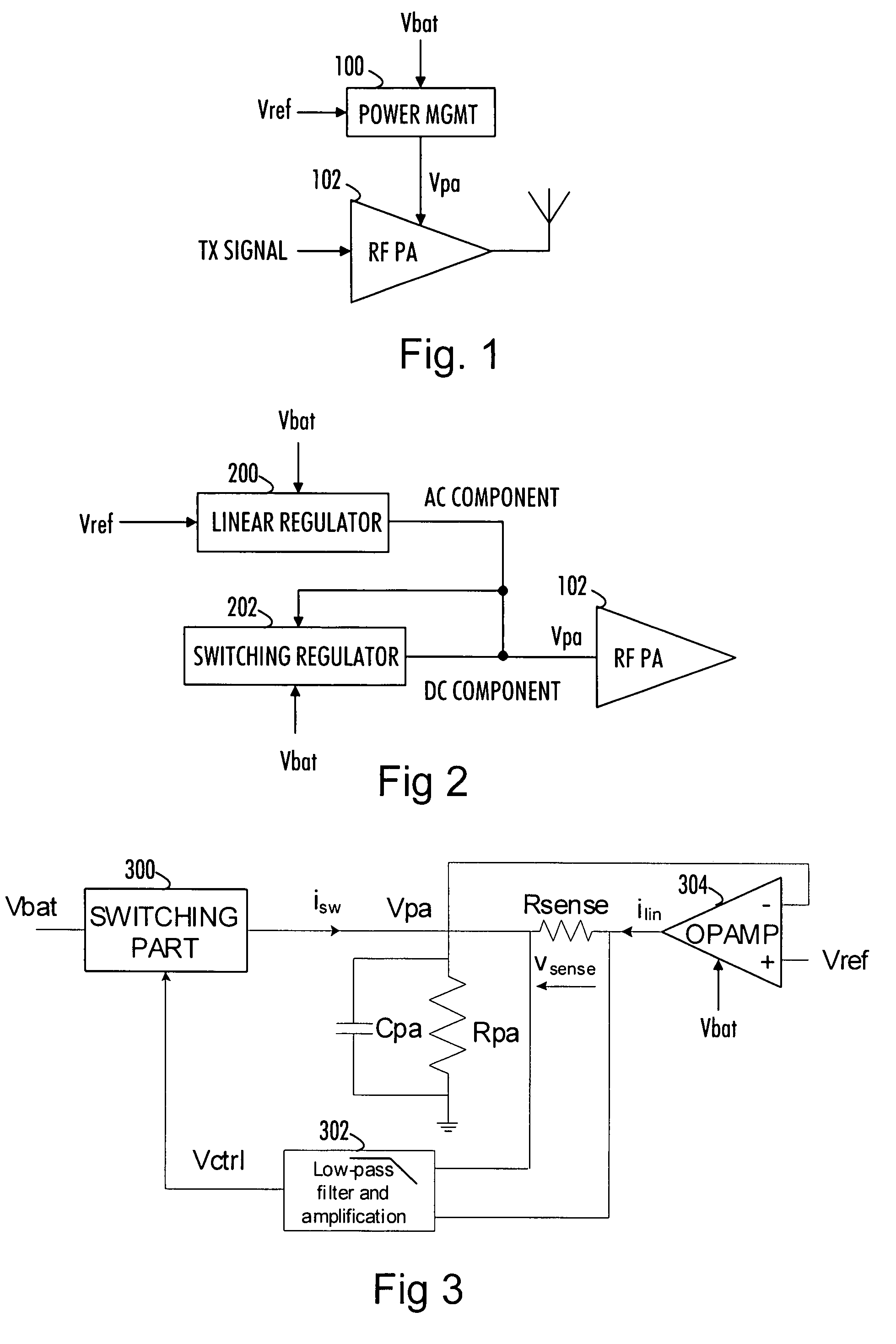
[0025]In principle, the efficiency of a parallel-hybrid amplitude modulator is optimum when an average output current, i.e. direct current (DC), of the linear part is zero. The overall efficiency would be severely degraded if the linear part would sink / source a DC component. Embodiments of the invention aim to control the switching part to compensate for the level of a DC component at an output of the linear part in order to minimize the absolute level of the average output current of the linear part, i.e. to prevent the linear part from becoming a source or a sink of DC current. In other words, the average output current of the linear part is minimized, i.e. kept as close to zero as possible. The basic structure of the parallel-hybrid amplitude modulator according to embodiments of the invention is similar to that illustrated in FIG. 2 but the embodiments comprise additional advantageous aspects. The parallel-hybrid amplitude modulator may form a switched-mode power supply providin...


PUM


Abstract

A power management device providing a power amplifier with power supply voltage is provided. The power management unit includes a parallel-hybrid amplitude modulator apparatus having a linear part configured to track frequency components of an input signal above a determined threshold frequency and a switching part arranged in parallel with the linear part and configured to track frequency components of the input signal below the determined threshold frequency. Additionally, the power management unit includes a current sensing and controlling part configured to determine the level of a direct current component at an output of the linear part and control the switching part to produce an output signal compensating for the direct current component at the output of the linear part to decrease the absolute level of the direct current at the output of the linear part.

Description

FIELD[0001]The invention relates generally to radio devices and particularly to controlling a multi-mode amplitude modulator providing a power amplifier with power supply.BACKGROUND[0002]In radio transmitters, a transmission signal, i.e. the signal being transmitted, is amplified in a radio frequency power amplifier which amplifies the transmission signal to a level suitable for transmission over an air interface to a radio receiver. The level of the power-amplified transmission signal should be high enough to enable the radio receiver to decode information contained in the transmission signal.[0003]In order to improve the power-efficiency of the power amplifier, a power supply voltage applied to the power amplifier is an amplitude-modulated signal adapted to track an envelope or an amplitude component of a radio frequency transmission signal amplified by the power amplifier. FIG. 1 illustrates a radio transmitter arrangement comprising a power amplifier 102 and a power management d...

Claims


Application Information

Patent Timeline
Patent Type & Authority Patents(United States)
IPC IPC(8): H03C1/00
CPCH03F1/0205H03F1/0211H03F3/24H03F3/68H03F2200/324H02M2001/0045H03F2200/462H03F2200/481H03F2200/504H03F2200/507H03F2200/432H03F2200/351H02M1/0045
Inventor IMMONEN, ANTTIGRIGORE, VLAD
Owner NOKIA TECH OY
Learn More