
Optical packet communication system using labeling of wavelength-offset polarization-division multiplexing

a wavelength-offset polarization and multiplexing technology, applied in multiplex communication, data switching networks, instruments, etc., can solve the problems of difficult to embody the label swapping device, complicated label swapping process, and label swapping device swapping, and achieve stable labeling and low cost

Inactive Publication Date: 2009-05-26
SAMSUNG ELECTRONICS CO LTD
View PDF9 Cites 6 Cited by
  • Summary
  • Abstract
  • Description
  • Claims
  • Application Information

AI Technical Summary

Benefits of technology

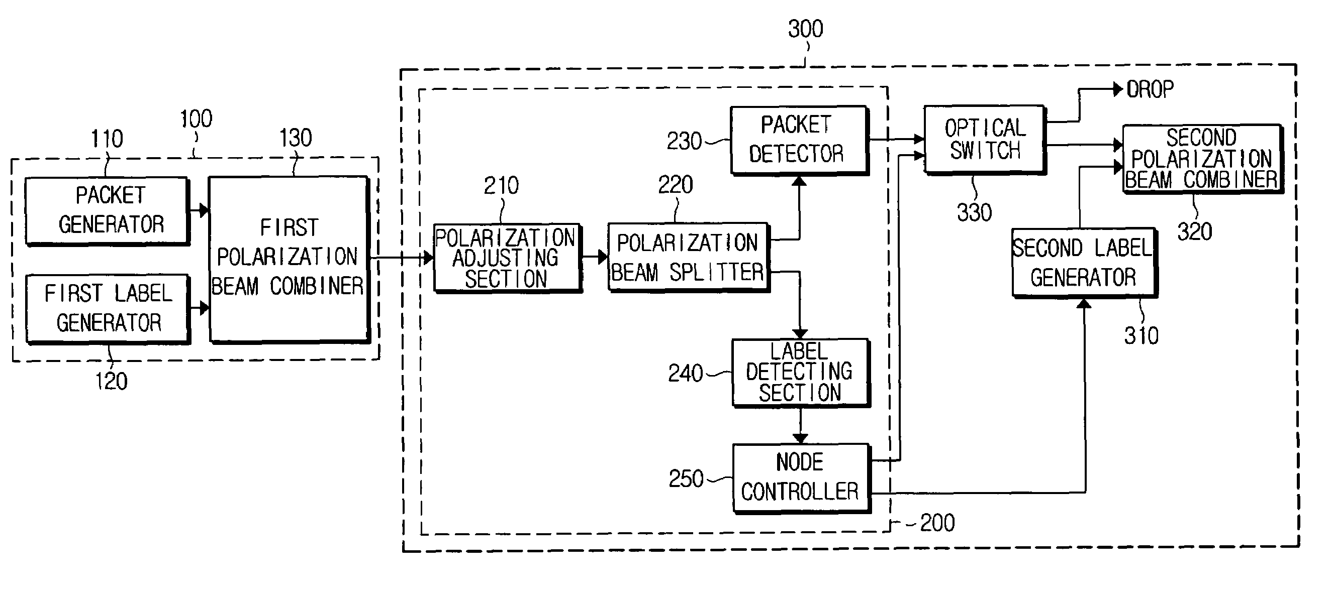
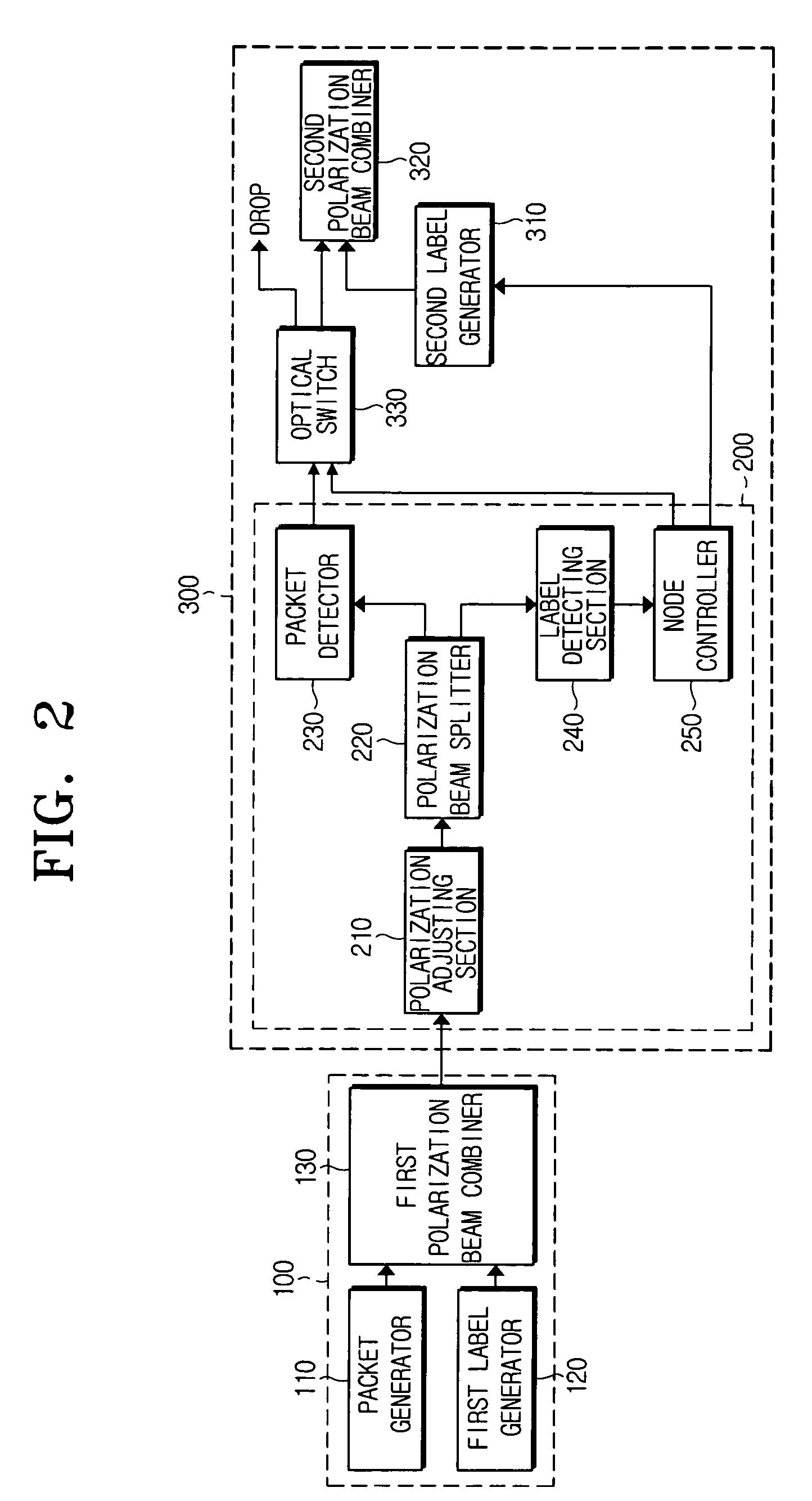
The present invention provides an optical packet communication system that uses a wavelength-offset polarization-division multiplexing labeling to perform stable labeling at a low cost. The system reduces beating noise and polarization dependence loss to prevent optical signal deterioration. The system includes an optical signal transmitter for generating and combining packet data and a label, and a label swapping device for detecting the label, generating a new label, and combining the new label with the packet data. The system also includes a polarization beam splitter for dividing the optical signal into vertical and horizontal polarization components, a packet detector for receiving the packet data, a label detecting section for obtaining next moving information of the optical signal, and a node controller for controlling an optical switch to move the packet data to a position recorded in the label. The technical effects of the invention include stable labeling, reduced beating noise, and improved signal quality.

Problems solved by technology

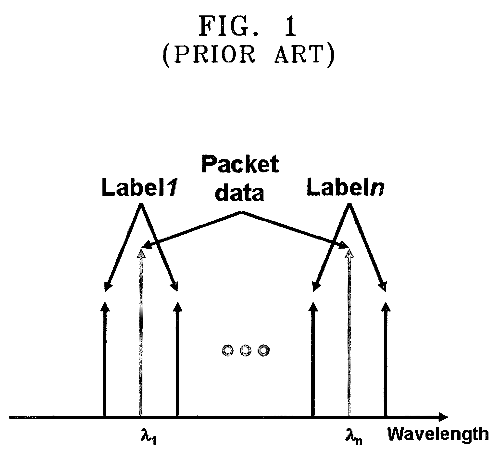
In such a sub-carrier multiplexing labeling, a label swapping device is very complicated, and it is thus difficult to embody the label swapping device.
This causes a label swapping process to be complicated.

Method used


Image

  • Optical packet communication system using labeling of wavelength-offset polarization-division multiplexing
  • Optical packet communication system using labeling of wavelength-offset polarization-division multiplexing
  • Optical packet communication system using labeling of wavelength-offset polarization-division multiplexing

Examples


Embodiment Construction

[0027]The present invention will now be described with reference to the accompanying drawings, in which exemplary embodiments of the invention are shown. However, this invention should not be construed as limited to the embodiments set forth herein. Rather, these embodiments are provided so that this disclosure will be thorough and complete, and will fully convey the scope of the invention to those skilled in the art. Like numbers refer to like elements.

[0028]FIG. 2 is a block diagram showing a configuration of an optical packet communication system using a wavelength-offset polarization-division multiplexing labeling in accordance with an embodiment of the present invention. Referring to FIG. 2, the optical packet communication system using a wavelength-offset polarization-division multiplexing labeling in accordance with an embodiment of the present invention includes an optical signal transmitter 100 and a label swapping device 300.

[0029]The optical signal transmitter 100 is prov...


PUM


Abstract

Disclosed is an optical packet communication system using a wavelength-offset polarization-division multiplexing labeling. An optical signal transmitter which is provided at an ingress node positioned at a sending end in an optical packet switching network, generates and combines packet data and a label, and transmits the combined packet data and label to a core node, wherein the packet data and label have polarization directions perpendicular to each other and maintain a predetermined wavelength interval. A label swapping device detects the label from the combined packet data and label received from the optical signal transmitter, detects next moving position information of the packet data, for generating a new label, substitutes the detected label by the new label, combines the new label with the packet data, and transmits the combined packet data and new label to a next moving position.

Description

CROSS-REFERENCE TO RELATED APPLICATIONS[0001]The application claims benefit under 35 U.S.C. § 119 from Korean Patent Application No. 2004-88348, filed on Nov. 2, 2004, the entire content of which is incorporated herein by reference.BACKGROUND OF THE INVENTION[0002]1. Field of the Invention[0003]The present invention relates to an optical packet communication system using a wavelength-offset polarization-division multiplexing labeling. More particularly, the present invention relates to an optical packet communication system using a wavelength-offset polarization-division multiplexing labeling, which maintains a wavelength interval between packet data and a label constant to reduce a beating noise, thereby preventing deterioration of performance of an optical signal.[0004]2. Description of the Related Art[0005]In an optical packet switching network, each node includes an ingress node, a core node, and an egress node, wherein a sending end is positioned at the ingress node and a recei...

Claims


Application Information

Patent Timeline
Patent Type & Authority Patents(United States)
IPC IPC(8): H04J14/06H04J14/00H04J4/00H04B10/27G02B27/28H04B10/2507H04B10/291H04L12/70H04L12/701
CPCH04J14/06H04Q11/0005H04Q11/0066H04Q2011/0035H04Q2011/0039
Inventor PARK, KEUN-JOOKIM, HYUN-CHINRHEE, JUNE-KOOSEO, YOUNG-KWANGYOUN, CHUN-JU
Owner SAMSUNG ELECTRONICS CO LTD
Learn More