Method and apparatus for determining a predicted failure rate

a technology of failure rate and prediction method, applied in the field of prediction failure rate, can solve problems such as the installation of additional redundancy and the trigger of some service action

Active Publication Date: 2009-05-26
ORACLE INT CORP
View PDF4 Cites 128 Cited by
  • Summary
  • Abstract
  • Description
  • Claims
  • Application Information

AI Technical Summary

Benefits of technology

[0005]Accordingly, one embodiment of the invention provides a method of determining a predicted failure rate in a system comprising multiple components, where the system provides one or more computational resources. The method comprises storing failure rate information about individual components and determining a current configuration of components within the system. The method further comprises identifying from the current configuration dependencies between components within the system. The stored failure rate information and the identified current configuration dependencies are then used to generate a predicted failure rate for each of the computational resources provided by the system in its current configuration.

Problems solved by technology

The system may also trigger some service action, such as the installation of additional redundancy, if a predicted failure rate is found to be too low to provide the desired level of service availability.

Method used


Image

  • Method and apparatus for determining a predicted failure rate
  • Method and apparatus for determining a predicted failure rate
  • Method and apparatus for determining a predicted failure rate

Examples


Embodiment Construction

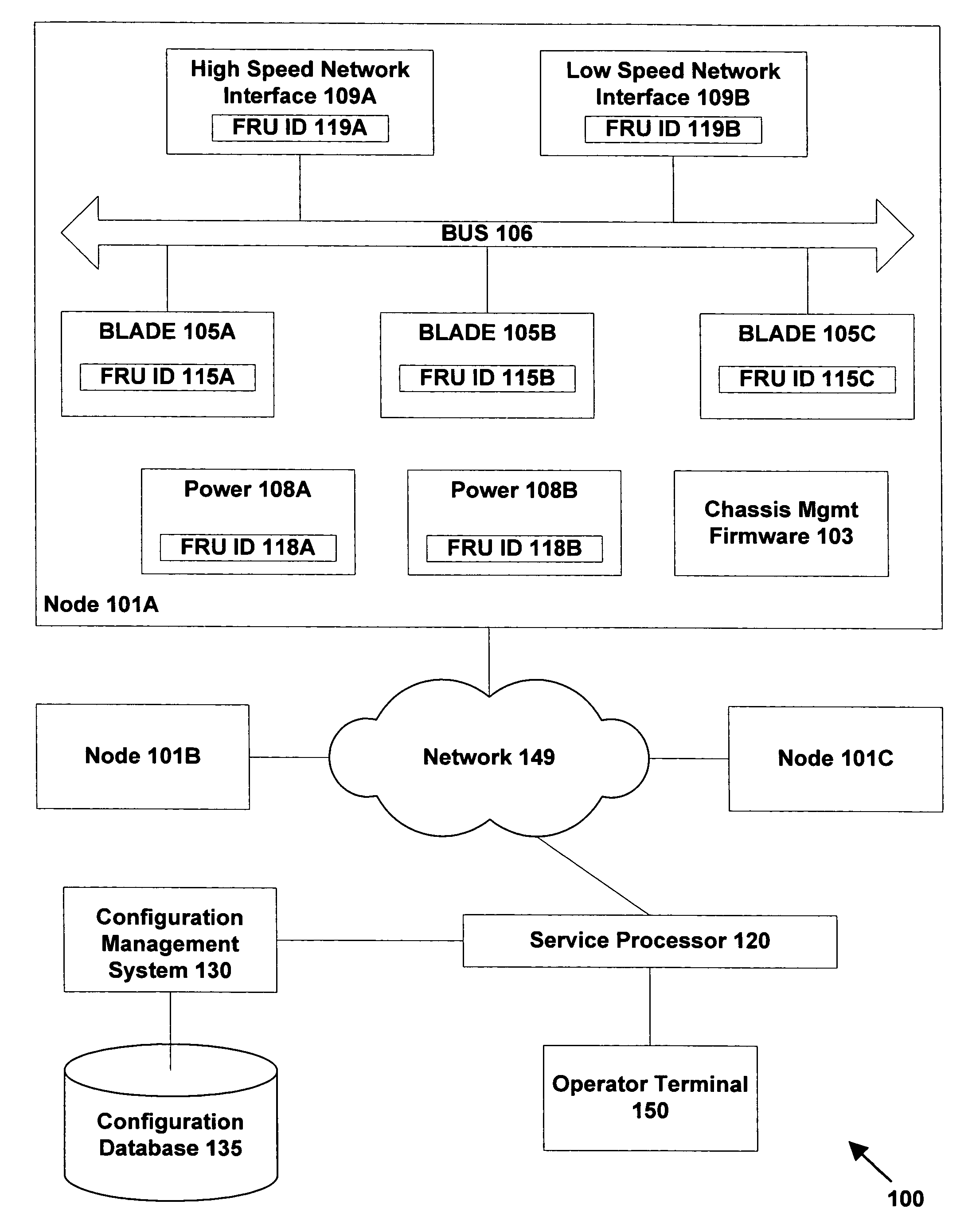
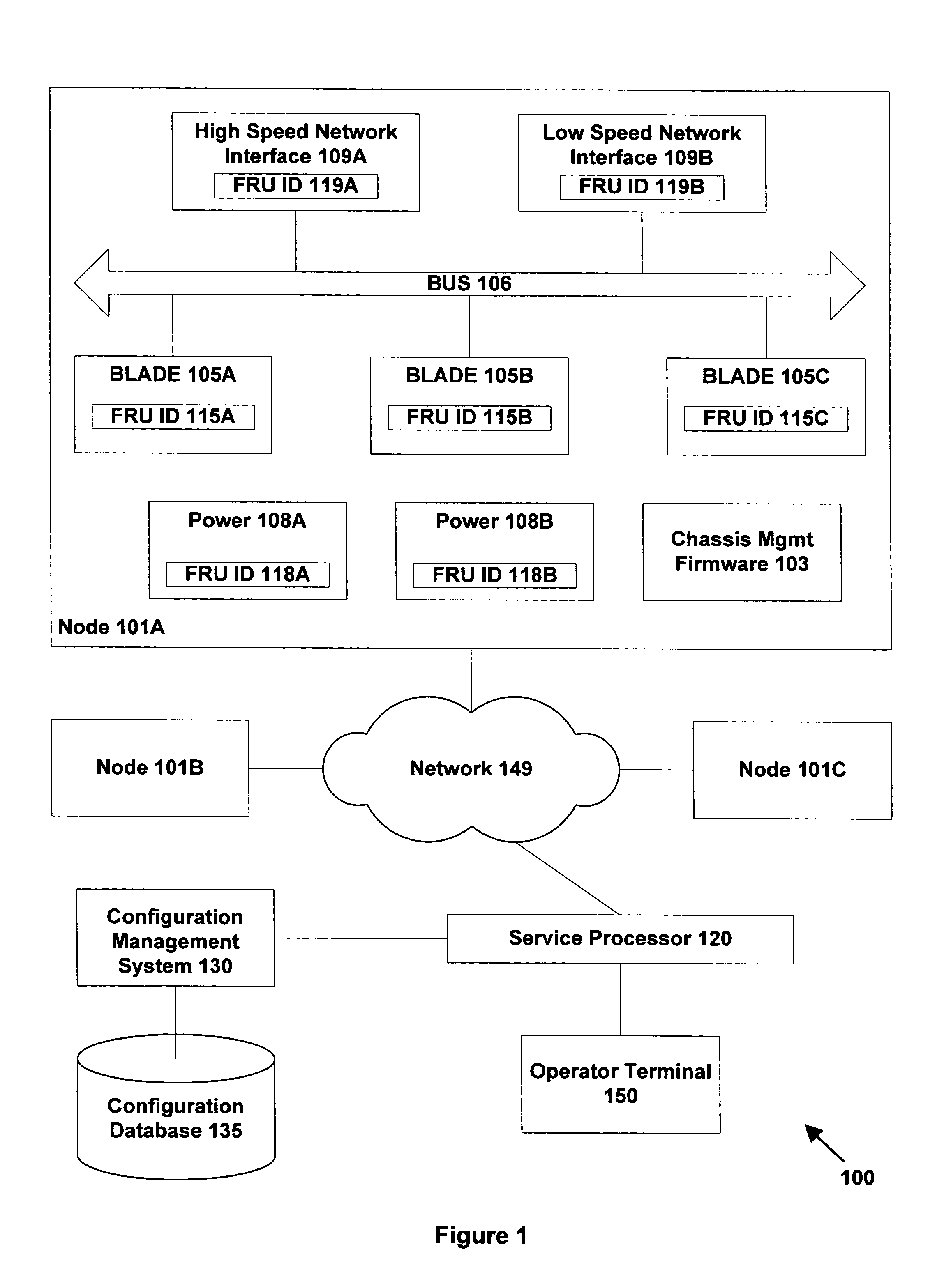
[0023]FIG. 1 is a schematic illustration of a computer system 100 in accordance with one embodiment of the invention. Computer system 100 comprises multiple nodes 101A, 101B, and 101C linked by computer network 149. Computer system 100 may represent a variety of possible architectures. For example, in one embodiment, nodes 101 may represent individual subsystems within a single distributed computer system. In another embodiment, nodes 101 may represent individual servers in a cluster of servers managed as a single group. In another embodiment, nodes 101 may represent communications nodes (switches or end-points) within network 149, in which case system 100 may correspond to the overall network. It will be appreciated that other systems may have more or fewer nodes than system 100 as shown in FIG. 1; in addition, the topology of network connections between the nodes may vary as appropriate.

[0024]FIG. 1 illustrates components within one node 101A in more detail (for clarity the intern...


PUM


Abstract

A method and apparatus for determining predicted failure rates for computational resources provided by a system comprising multiple components. The method comprises storing failure rate information about individual components and determining a current configuration of components within the system. The method further comprises identifying from the current configuration dependencies between components within the system. The stored failure rate information and the identified current configuration dependencies can then be used to generate predicted failure rates for the computational resources in the current configuration of the system.

Description

FIELD OF THE INVENTION[0001]The present invention relates to predicting failure rates, for example in a computer system or a communications network.BACKGROUND OF THE INVENTION[0002]System reliability is very important in the computing field. A common approach for providing good reliability or availability in computing is through the use of redundancy, in which two or more components are provided to perform a given task. If one of these components fails, the remaining component(s) are still available to ensure that the task is performed. Incorporating redundancy into a system however adds to the expense of the system. Consequently, it is undesirable to replicate a component within a system if such replication has only a slight or no impact on the reliability and availability of the resulting system.[0003]An assessment of availability is usually based on a statistic such as the mean time between failure (MTBF) or the average (or annualised) failure rate (AFR). The AFR inherently expre...

Claims


Application Information

Patent Timeline
Patent Type & Authority Patents(United States)
IPC IPC(8): G06F11/00
CPCG06F11/008
Inventor JOHNSEN, BJORN DAGOPHEIM, HANS LUDWIGHODOBA, PREDRAGHUSE, LARS PAUL
Owner ORACLE INT CORP
Why Eureka
Try Eureka