Method and apparatus for providing power

a technology of power supply and power supply, applied in the direction of dc-ac conversion without reversal, plasma technique, transmission system, etc., can solve the problems of high manufacturing cost, high energy consumption, and long sterilization time, and achieve the effect of reducing voltage, less time, and increasing reliability

Active Publication Date: 2014-11-27
UNIV OF FLORIDA RES FOUNDATION INC
View PDF1 Cites 14 Cited by
  • Summary
  • Abstract
  • Description
  • Claims
  • Application Information

AI Technical Summary

Benefits of technology

[0017]FIG. 23 shows the logic truth table that is used to select a cell. FIG. 23 also shows that only two power amplifiers need to operate at once. In a specific embodiment, the m+n power amplifiers can be replaced by only two power amplifiers, or a number of power amplifiers between 2 and m+n. High voltage mechanical relays can be employed to connect the top and bottom electrodes to the two or more power amplifiers, in an embodiment having fewer than m+N power amplifiers. However, the relays may not fully turn off a cell. In an embodiment, each cell has a capacitance of approximately 8 pF while each relay has between 2 and 3 pF (depending on brand). As these impedances are comparable, a relay will likely not fully switch off a cell, making the use of mechanical relays less desirable for this application. Further, mechanical relays may be less reliable as well. In addition, by using m+n power amplifiers, the time spent driving the work is distributed among all the Pas and will not be running during the whole sterilization time. This increases reliability given each PA operates for less time.
[0018]In an embodiment, when plasma is generated across a single cell, the adjacent cells do present some voltage across them. This can occur because the electrodes being powered cover a complete row and column as shown in FIG. 24A. However, this voltage or adjacent cells decays along the row (or column) and does not generate plasma across the adjacent cells. Accordingly, the power consumed by the voltage across adjacent cells is not significant. FIG. 24A shows that plasma across cell (0,1) is generated by enabling power amplifier 1 and power amplifier 6, while FIG. 24B shows the voltage across adjacent cells decays to a low value that is not high enough to produce plasma, such that power loss across adjacent cells is not significant. To further reduce the voltage across the adjacent cells, the material used as the substrate can have electrical properties that increase the decaying of the electric field more rapidly.
[0019]In a specific embodiment, the size of each cell is approximately 1″ by 1″. In additional embodiments, the cells can be made much smaller (e.g., 0.1″ by 0.1″), if desired. With embodiments having smaller cells for the same overall surface area, the number of power amplifiers can increase, while the power requirement per cell decreases. In this way, the power needed to generate plasma across a certain surface area is divided among more power amplifiers. Since power requirements per power amplifier decreases, components can be reduced in size. Also, using smaller cells increases the “resolution” of the surface plasma. This is the same concept as the pixels on a computer screen. The more pixels, the better the resolution. For a plasma sterilizer, the more resolution, the more efficient the system can be is at generating plasma only across the contaminated cells.

Problems solved by technology

These methods require a high amount of energy and lead to high manufacturing costs.
However, it requires long sterilization times (˜20-40 min), longer standing times, and a large infrastructure.
Each of these requires expensive infrastructure and long periods of time to achieve complete sterilization.
In some applications, for example in high-speed air vehicles, this is an impractical limitation.
Power supply units that drive dielectric barrier discharge devices like plasma actuators and plasma sterilization devices are heavy and bulky weighing several kilograms occupying several square feet of footprint.
However, it consists of 4 transistors and large passive components, making it bulky.
However, these designs are not efficient and do not produce power outputs high enough for plasma generation.

Method used


Image

  • Method and apparatus for providing power
  • Method and apparatus for providing power
  • Method and apparatus for providing power

Examples


example 1

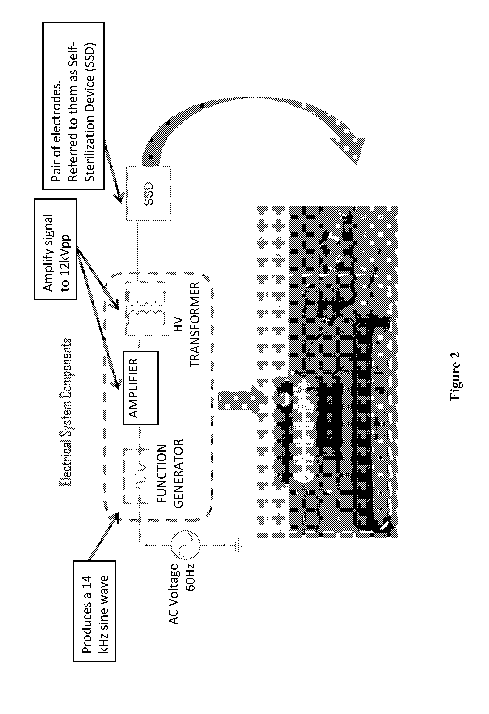
[0113]Referring to FIG. 5, a self-sterilizing device (SSD) including electrodes separated by a dielectric material is shown. Such a SSD can be used as a load for a power supply unit of the subject invention. The size of the SSD in FIG. 5 is 1.5 inches wide by 1.5 inches long.

[0114]Using an impedance analyzer (HP 4192A LF), the impedance of the device was measured to be 7 pF with high resistance (MΩ range). However, this is a low signal impedance measurement, which changes when plasma is generated on the SSD.

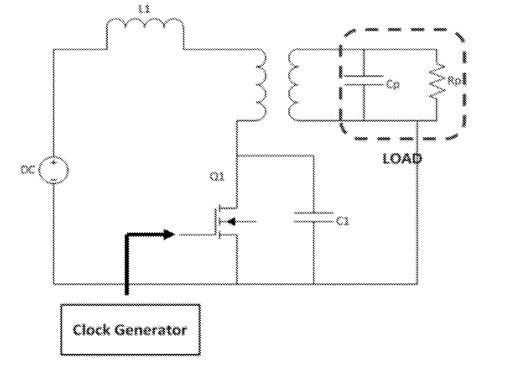
[0115]FIG. 6 shows an example of a load model for high frequency operation. The values of CP and RP were determined using Equations (1) and (2). IO and QO were determined from their respective Lissajous diagrams, which are obtained from experimental data. The setup used to extract these two values is shown in FIG. 7. Using FIG. 8 and Equations (1) and (2), CP and RP were evaluated as 11 pF and 1.2 MΩ, respectively.

CP=IO / (2πfVg)  (1)

RP=Vg / (2πfQO)  (2)

[0116]The system must be able ...


PUM


Abstract

Embodiments of the subject invention are drawn to power supply units and systems for supplying power to loads. Specific embodiments relate to systems incorporating the loads. The power supply units and systems can include a feedback mechanism for monitoring the system and maintaining a parameter of interest at or near a desired value (e.g., for maintaining the frequency of operation at or near resonance). The feedback mechanism is configured such that, if the at least one parameter indicates that the frequency of operation is away from a resonant frequency of the power amplifier, the feedback mechanism adjusts the frequency of operation closer to the resonant frequency of the power amplifier. The at least one load can have a variable impedance, though embodiments are not limited thereto.

Description

CROSS-REFERENCE TO RELATED APPLICATION[0001]The present application claims the benefit of U.S. Provisional Application Ser. No. 61 / 580,083, filed Dec. 23, 2011, which is hereby incorporated by reference in its entirety, including any figures, tables, or drawings.BACKGROUND OF INVENTION[0002]Solid state flow control devices are in high demand for moderate to high flow speeds. Such devices can have several important applications. Current solid state flow control devices operate using arc filament and / or arc heating flow control methods. These methods require a high amount of energy and lead to high manufacturing costs.[0003]The generation of plasma due to electrical input has important applications. The basic mechanisms inherent in non-equilibrium discharges such as obtained through DC, RF, or microwave excitation have also been utilized for ionization purposes, so as to increase the conductivity of air for further control with ponderomotive forces generated with an imposed magnetic f...

Claims


Application Information

Patent Timeline
Patent Type & Authority Applications(United States)
IPC IPC(8): H02M7/44H02M1/08H01J37/32
CPCH02M1/08H02M2001/0003H02M7/44H01J37/32348Y02B70/1441H05H2001/4682H02M7/53803Y10T307/406H02M2007/4815H05H1/46Y02B70/10H02M7/4815H05H2242/22H02M1/0003
Inventor CHINGA, RAUL ANDRESZAWOY, KARL R.ROY, SUBRATALIN, JENSHAN
Owner UNIV OF FLORIDA RES FOUNDATION INC
Why Eureka
Try Eureka