Eureka AIR delivers breakthrough ideas for toughest innovation challenges, trusted by R&D personnel around the world.

Modular fixture and sports lighting system

a technology of sports lighting and modules, applied in lighting applications, lighting support devices, instruments, etc., can solve the problems of uniformity loss, parts of fixtures cannot be turned off to conserve energy, local dimming regions on the field, etc., and achieve the effect of facilitating assembly and lighting system installation

Inactive Publication Date: 2009-06-02
GENERAL ELECTRIC CO
View PDF35 Cites 24 Cited by
  • Summary
  • Abstract
  • Description
  • Claims
  • Application Information

AI Technical Summary

Benefits of technology

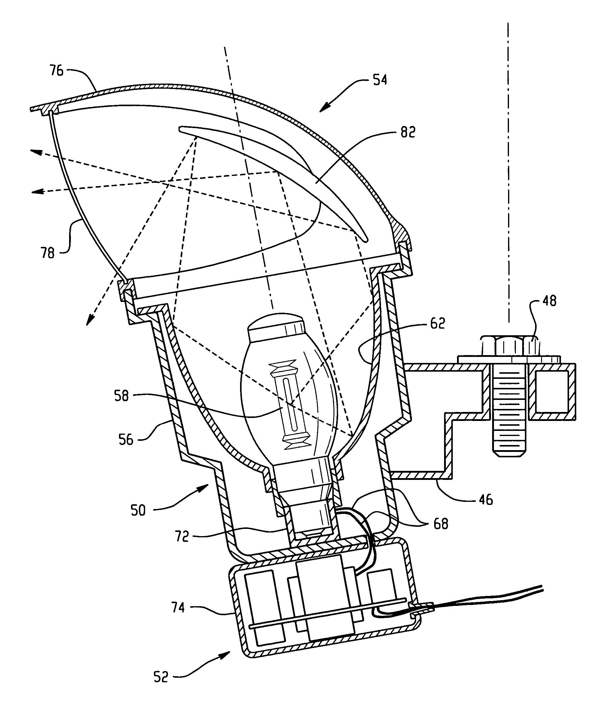
[0006]A modular light fixture primarily for use in sports lighting applications, but with features that are potentially useful in general outdoor area and indoor lighting applications, includes a light engine serving to provide a generally converging beam of light onto which an application specific photometric module is attached. The photometric module distributes light so that a photometric pattern is created that covers the entire playing surface. To achieve the desired light levels, multiple duplicate fixtures using identical engines can be used. Application specific photometric modules that are typically designed as right hand and left hand modules are pointed in the same general direction are used in superposition. This allows the lighting design for specific applications to be standardized. Modular construction facilitates assembly and lighting system installation. Additionally, the fixture can be configured to provide the photometric characteristics of the typical NEMA classifications used currently in most sports lighting installations.

Problems solved by technology

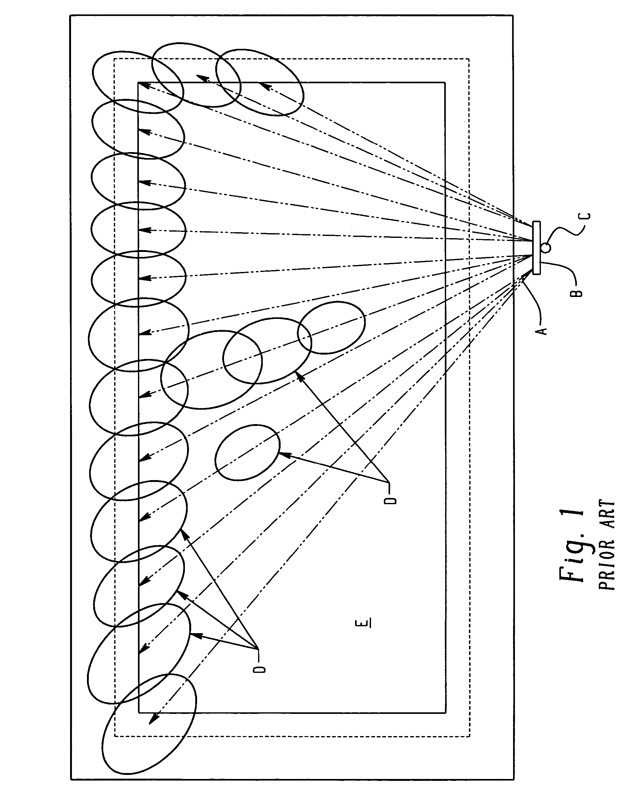
Lamp failures in individual fixtures cause local dimmed regions on the field and uniformity loss.
Also, portions of the fixtures cannot be turned off to conserve energy without creating dimmed regions on the field.
This, of course, becomes a time consuming and expensive task.
In general, the economics of purchase and operating costs drive the design to use the minimum number of fixtures necessary to meet the light level and uniformity requirements.
This substantially limits or precludes redundancy in light coverage on the field and if one fixture fails, a region of low light level results in the area that was illuminated by the light emitted from the failed fixture.

Method used


Image

  • Modular fixture and sports lighting system
  • Modular fixture and sports lighting system
  • Modular fixture and sports lighting system

Examples


Embodiment Construction

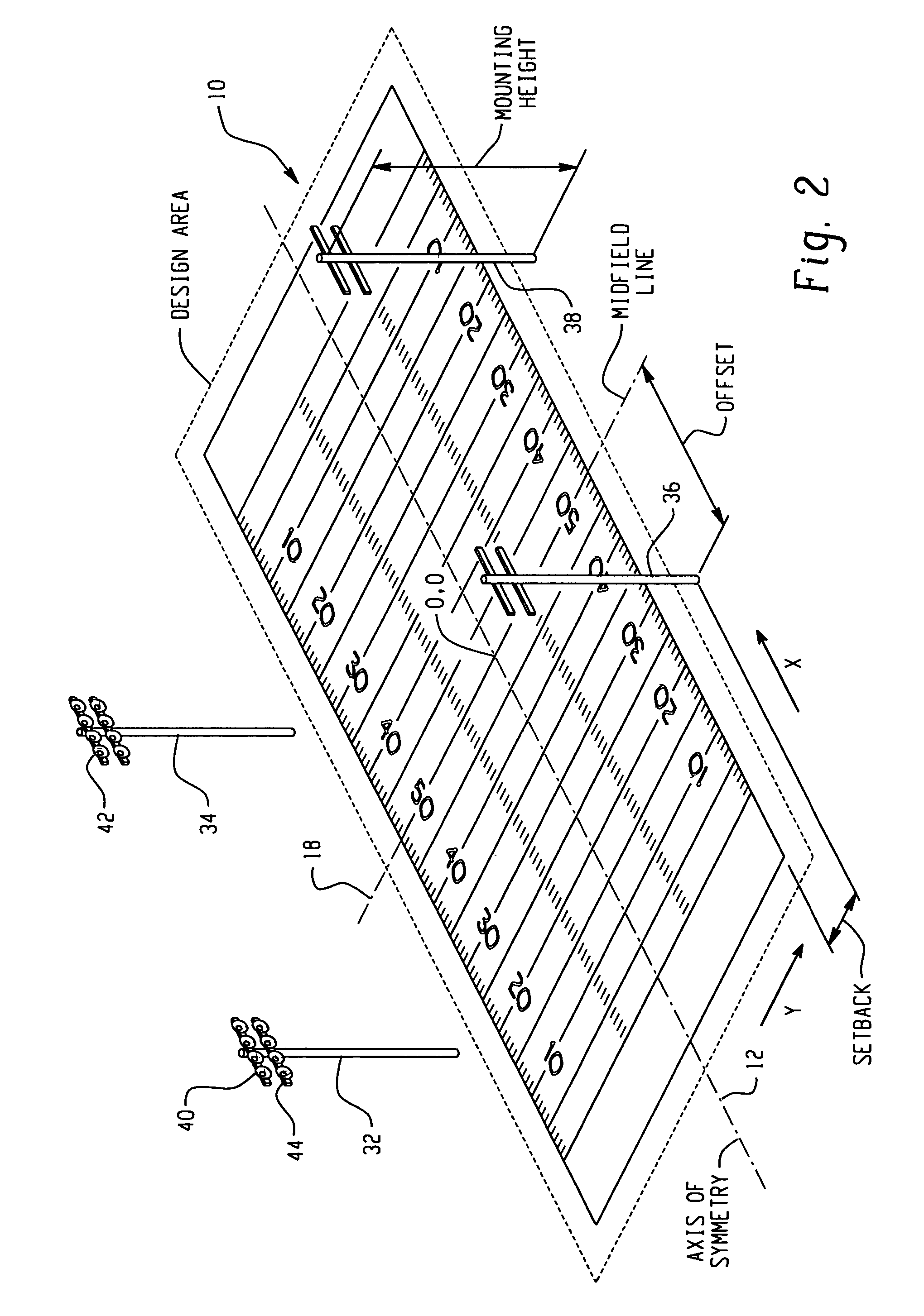
[0021]With reference to FIG. 2, a subject area 10 is illuminated by a plurality of lights. For the sake of brevity and understanding, the subject area 10 in this portion of the description is a football field, however it is to be understood that the subject area could be any recreation field or large area including, without limitation, a baseball field, a softball field, a soccer field, a recreation field, an arena floor, a tennis court, an exercise floor, a gymnasium floor, or a parking lot.

[0022]Facilities, such as playing fields, are designed according to certain illumination criteria. The lighting level illumination criteria are usually measured in foot candles (“fc”). As just one example, class II football requires 50 fc horizontal and 40 fc vertical. The classes and the lighting level are well known in the art and need not be described in further detail.

[0023]In addition to the lighting level, another illumination criterion is the uniformity of lighting throughout the playing ...


PUM


Abstract

A light fixture includes a lamp engine, an electronic module connected to the lamp engine and a photometric module mounted to the light engine. The electronic module is connected to the light source and an associated power source for providing power to the light source. The photometric module mounts to the light engine and creates a beam pattern that illuminates a substantial portion of an entire associated subject area. The method of illuminating a large area includes determining a subject area to be illuminated by a plurality of light sources and determining a desired lighting criteria for the subject area. A first light source is provided and light emitted from the first light source is directed to illuminate the subject area. Additional light sources are provided and directed to provide additional light to illuminate the same portion of the subject area until the desired lighting criteria are met.

Description

BACKGROUND OF THE INVENTION[0001]This invention relates to illumination devices. More particularly, the invention relates to illuminating a large surface area or playing surface such as a sports or recreation field. The invention is also amenable to other applications including lighting parking lots, as well as other large areas including indoor areas.[0002]Existing sports lighting installations normally comprise several poles and a multiplicity of similar fixtures that are typically the same wattage and model with different photometric characteristics. The fixtures are mounted on poles with cross-arms and individually aimed in such a way that the various photometric patterns fill in regions of the lighted area to meet the desired uniformity and light levels. In some applications this requires measuring the lighting results and pointing the fixtures at the time of installation to compensate for variations in the individual fixture photometry, photometric axis, and the inaccuracies o...

Claims


Application Information

Patent Timeline
Patent Type & Authority Patents(United States)
IPC IPC(8): F21V21/00F21V33/00
CPCF21S2/00F21V7/0008F21V7/0025F21V23/02F21W2131/10F21W2131/105F21W2131/407
Inventor STEINBERG, GARY A.
Owner GENERAL ELECTRIC CO
Why Eureka
Eureka Blog
Learn More