Condenser microphone

a condenser microphone and microphone body technology, applied in the direction of electrical transducers, transducer types, microphone structural associations, etc., can solve the problems of interfering with the operation of vacuum tubes, and achieve the effect of preventing the dc magnetization of the transformer cor

Inactive Publication Date: 2009-06-02
AUDIO-TECHNICA
View PDF5 Cites 5 Cited by
  • Summary
  • Abstract
  • Description
  • Claims
  • Application Information

AI Technical Summary

Benefits of technology

[0024]Therefore, it is an object of the present invention to prevent the DC magnetization of a transformer core without increasing the size of an output transformer in a condenser microphone which uses a vacuum tube as an impedance converter, outputs a vacuum tube signal via the output transformer, and is operated by a phantom power source.

Problems solved by technology

Thus, a typical phantom power source of DC 48 V cannot afford such a power and thus a dedicated power source is used.
For example, when a current of 10 mA passes through the heater of the vacuum tube, a voltage supplied from the phantom power source to a microphone is reduced by 34 V (5 mA×6.8 kΩ) to 14 V. In this state, the “B” power source is insufficiently supplied to the plate of the vacuum tube, and thus this state interferes with the operations of the vacuum tube.

Method used


Image

  • Condenser microphone
  • Condenser microphone
  • Condenser microphone

Examples


Embodiment Construction

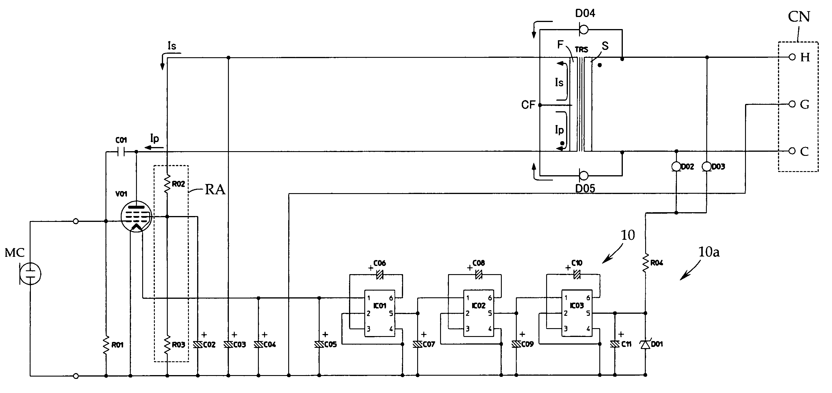
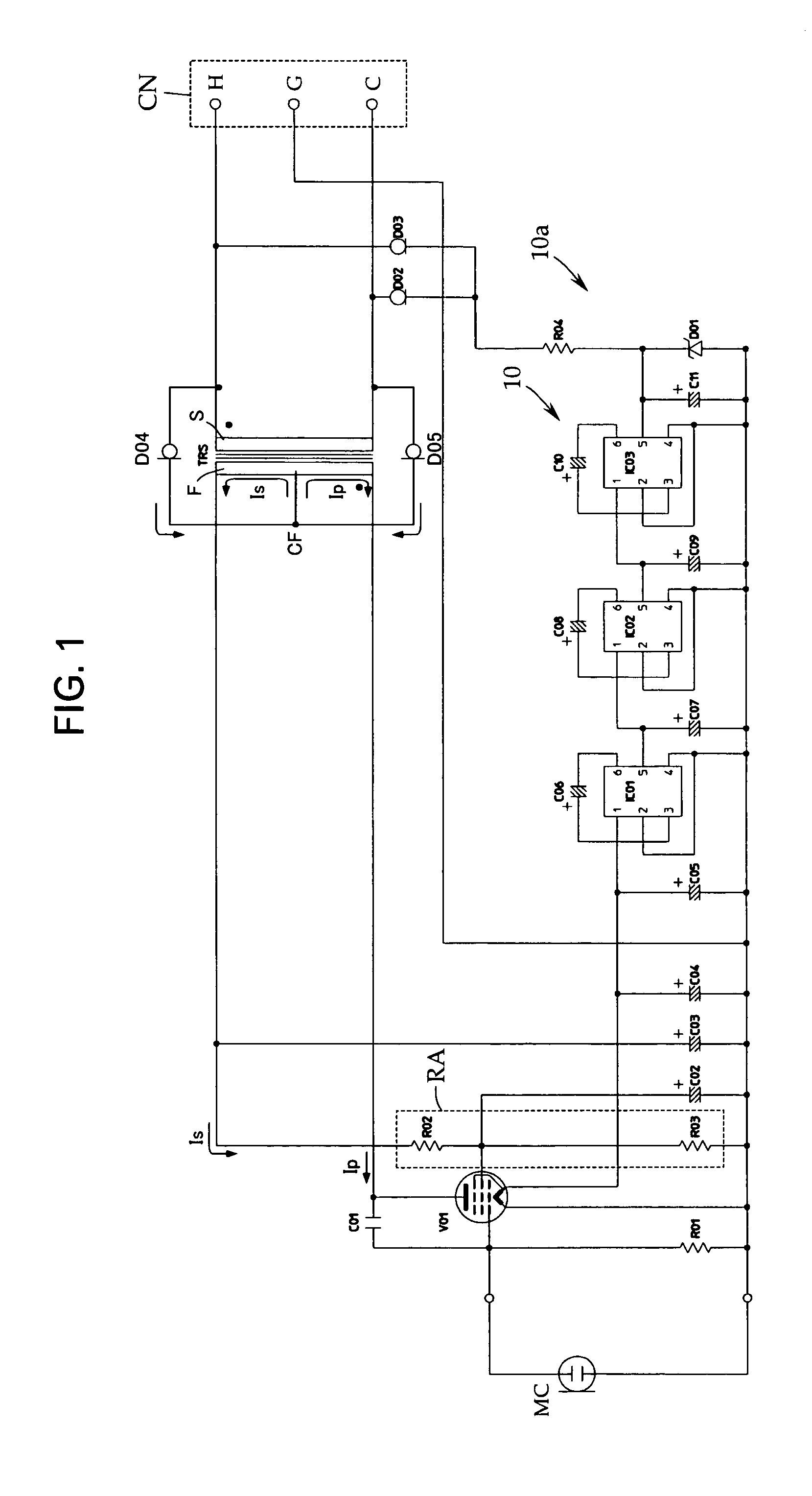
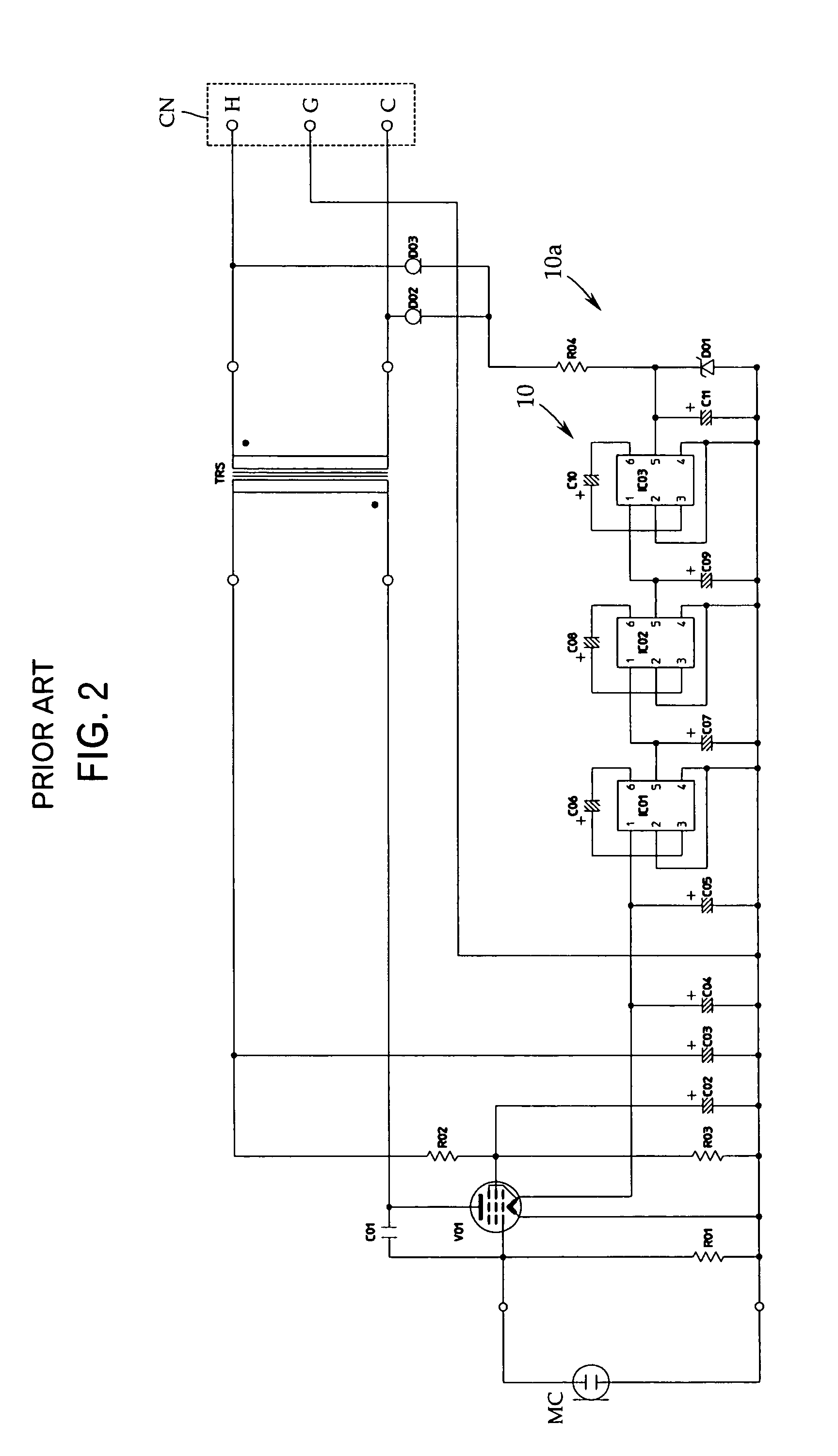
[0031]The following will describe an embodiment of the present invention with reference to FIG. 1, a circuit diagram of a microphone. The present invention is not limited to this embodiment. In the explanation of this embodiment, constituent elements particularly not to be changed from the invention of the prior application of FIG. 2 are indicated by the same reference numerals.

[0032]The condenser microphone of the present invention is operated by a phantom power source. The phantom power source is not shown because it is a publicly known power source having two 6.8-kΩ resistors connected in series between hot and cold of balanced transmission and a power source of DC 48 V connected between the ground and the joint of the resistors.

[0033]As shown in FIG. 1, the condenser microphone of the present invention is basically constituted of a condenser microphone capsule MC, a vacuum tube V01 serving as an impedance converter, an output transformer TRS, an output connector CN, and an “A” p...


PUM


Abstract

The DC magnetization of a transformer core is prevented without increasing the size of an output transformer in a condenser microphone which is operated by a phantom power source, uses a vacuum tube as an impedance converter, and outputs a vacuum tube signal via the output transformer. The condenser microphone includes a condenser microphone capsule MC, a vacuum tube V01 used as an impedance converter, and an output transformer TRS having a primary winding F connected to the plate and screen grid of the vacuum tube V01 and a secondary winding S connected to the phantom power source via an output connector, wherein the primary winding F has a center tap CF and both ends of the secondary winding S are connected to the center tap CF via constant current diodes D04 and D05, respectively.

Description

RELATED APPLICATIONS[0001]The present application is based on, and claims priority from, Japanese Application No. 2004-144841, filed May 14, 2004, the disclosure of which is hereby incorporated by reference herein in its entirety.TECHNICAL FIELD[0002]The present invention relates to a condenser microphone operated by a phantom power source, and more specifically to a condenser microphone using a vacuum tube as an impedance converter.BACKGROUND ART[0003]In a condenser microphone, an FET (field-effect transistor) or a vacuum tube is used as an impedance converter. This is because a condenser microphone capsule including a diaphragm and a fixed pole opposed to each other has quite a high impedance.[0004]When a vacuum tube is used as the impedance converter of a condenser microphone, generally a dedicated power source is necessary. Further, “A” power source for heating the heater of the vacuum tube and “B” power source for passing current through the plate of the vacuum tube are necessa...

Claims


Application Information

Patent Timeline
Patent Type & Authority Patents(United States)
IPC IPC(8): H04R3/00H04R1/04H04R19/00H04R19/04
CPCH04R1/04H04R19/00
Inventor AKINO, HIROSHI
Owner AUDIO-TECHNICA
Why Eureka
Try Eureka