
Narrow gap tungsten electrode argon arc welding technology method for thick plate

A technology of argon tungsten arc welding and welding process, applied in welding equipment, welding accessories, arc welding equipment and other directions, can solve the problems of low welding efficiency, limited range of gap width, complex equipment structure, etc., to achieve the effect of welding quality assurance

Active Publication Date: 2020-09-04
SHANDONG UNIV +1
View PDF8 Cites 6 Cited by
  • Summary
  • Abstract
  • Description
  • Claims
  • Application Information

AI Technical Summary

Problems solved by technology

[0003] At present, there are three main realization methods of narrow-gap tungsten argon arc welding: one is through the tilted tungsten electrode with straight tungsten electrode or double tungsten electrode double welding power structure, this structure can ensure effective side wall fusion, but the structure is complex and can be Welding gap width range is limited
One is to generate a swinging arc by swinging the inclined tungsten electrode in the gap to effectively heat the side walls on both sides, but there are also problems such as limited welding gap width and complex and expensive equipment structure.
The other is to control the heating range of the arc by means of external constraints, including the method of externally applying a transverse magnetic field and rotating the ceramic sheet to constrain the arc, but the magnetron arc method cannot weld easily magnetizable materials and needs to solve the problem of the magnetic field generation circuit. Rotating ceramics The welding efficiency of the sheet-constrained arc method is low, and the ceramic sheet needs to be replaced regularly, and there are also problems in the gas protection of the weld due to the introduction of air by the rotation of the ceramic sheet

Method used


Image

  • Narrow gap tungsten electrode argon arc welding technology method for thick plate
  • Narrow gap tungsten electrode argon arc welding technology method for thick plate
  • Narrow gap tungsten electrode argon arc welding technology method for thick plate

Examples


Embodiment 1

[0069] A thick plate narrow gap tungsten argon arc welding process, comprising the following steps:

[0070](1) Groove opening and groove treatment: 16Mn plate thickness 150mm, U-shaped groove on one side, 10mm narrow gap reserved, blunt edge reserved, rust removal at the groove; groove size: ① round bottom Arc transition radius R = 2.0mm; ② The protruding length of the blunt edge is 2.5mm, and the thickness of the blunt edge is 2.5mm; ③ The gap between the two sides is 1.0mm; ④ The groove angle is 0°;

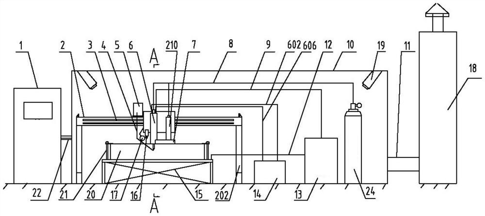
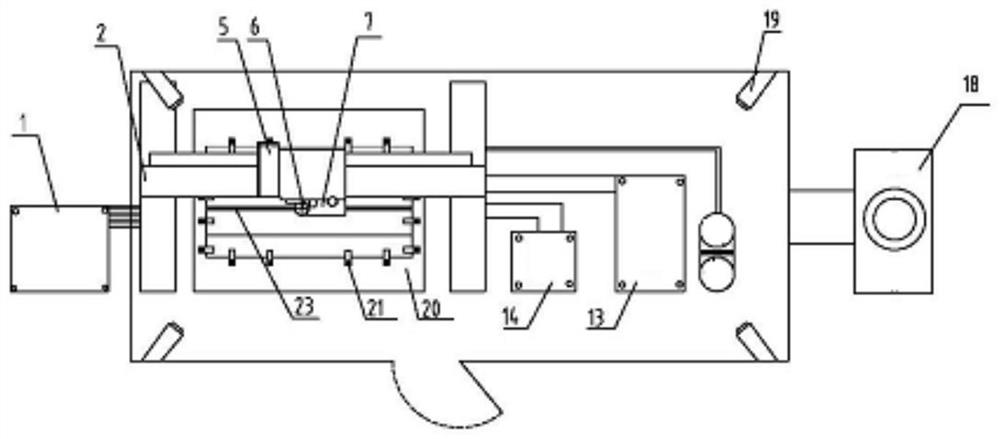
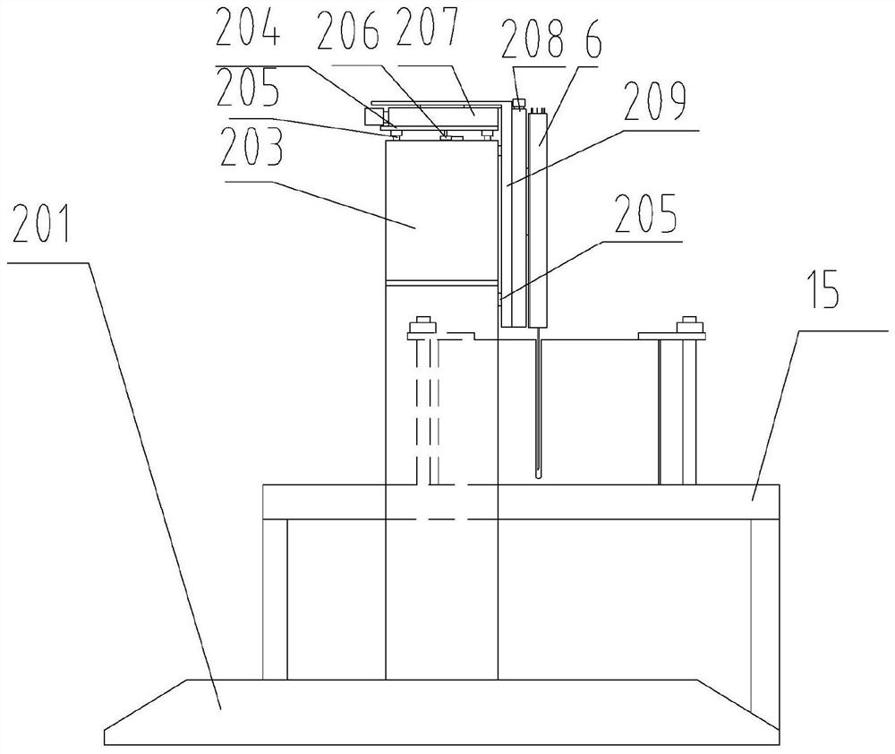
[0071] (2) Clamping: A narrow-gap tungsten argon arc welding equipment is used. The equipment includes a frame, a workbench, a welding torch, a wire feeding system, a water cooling system, a laser sensor, and an arc pressure sensor; the top of the welding torch passes through the air intake pipe and the gas cylinder. The top of the welding torch is connected to the welding power supply through the power wire. The water cooling system includes the water inlet pipe, the return p...

Embodiment 2

[0092] A thick plate narrow gap tungsten argon arc welding process, the steps are as described in embodiment 1, the difference is:

[0093] In step (1), the thickness of the 16Mn plate is 300 mm, U-shaped grooves are opened on both sides, and the gap width is 10 mm;

[0094] In step (2), the welding seam of the workpiece is fixed vertically downwards, and the method of vertical welding is adopted; two welding equipment are selected, respectively located on both sides of the workpiece, and welded vertically;

[0095] In step (3), a tungsten electrode with a diameter of 6.0 is selected, and the extension distance of the tungsten electrode is 150 mm;

[0096] In step (5), 50 layers are respectively welded on both sides of the 300mm thick plate, welding in layers, and the interlayer temperature is controlled below 100°C. The wire feeding speed is 260cm / min, the arc voltage is 18V, the welding current is 320A, the wire preheating current is 70A, the welding speed is 8cm / min, and t...

Embodiment 3

[0098] A thick plate narrow gap tungsten argon arc welding process, the steps are as described in Example 1, the difference is that in step (1), the groove size is: ① bottom arc transition radius R = 1.0mm ;②The protruding length of the blunt edge is 1.0mm, and the thickness of the blunt edge is 1.0mm;


PUM

PropertyMeasurementUnit
Diameteraaaaaaaaaa
Diameteraaaaaaaaaa

Abstract

The invention relates to a narrow gap tungsten electrode argon arc welding technology method for a thick plate, belongs to the technical field of narrow gap welding, utilizes narrow gap tungsten electrode argon arc welding equipment, and adopts a non-axisymmetric tungsten electrode rotation way to carry out the automatic welding of an ultra-thick plate (0-300 mm) and a narrow gap (4-10 mm). The narrow gap tungsten electrode argon arc welding technology method comprises the following steps of: (1) arranging a groove, and carrying out groove processing; (2) clamping the narrow gap tungsten electrode argon arc welding equipment; (3) installing the tungsten electrode, and carrying out equipment programing; (4) positioning: moving the tip of the welding gun tungsten electrode to the bottom of the center of a welding line, enabling a gas hood to be covered above the welding line, and then, through laser distance measurement, carrying out second positioning; (5) carrying out welding line backing weld: in a welding process, carrying out arc pressure and laser tracking to guarantee that the tungsten electrode is centered, utilizing an alternating current pulse hot filament TIG (Tungsten Inert Gas Welding) technology, and regulating welding current and pulse frequency to accurately control the heat input of the welding line; (6) carrying out layered filling weld; and (7) carrying out cosmetic weld. Compared with common tungsten electrode argon arc welding, the narrow gap tungsten electrode argon arc welding technology method disclosed by the invention greatly increases weldable platethickness and improves production efficiency and production quality.

Description

technical field [0001] The invention relates to a thick plate narrow-gap tungsten argon arc welding process and belongs to the technical field of narrow-gap welding. Background technique [0002] Narrow gap welding (NGW) is mainly used in thick plate welding. Before welding, the position of the welded joint is not beveled or beveled at a small angle, and a narrow and deep gap is left. The traditional welding method is adopted. Realize high-efficiency welding of workpieces. [0003] At present, there are three main realization methods of narrow-gap tungsten argon arc welding: one is through the tilted tungsten electrode with straight tungsten electrode or double tungsten electrode double welding power structure, this structure can ensure effective side wall fusion, but the structure is complex and can be The gap width range for welding is limited. One is to generate a swinging arc by swinging the inclined tungsten electrode in the gap to effectively heat the side walls on b...

Claims


Application Information

Patent Timeline
IPC IPC(8): B23K9/167B23K9/235B23K9/32B23K9/133
CPCB23K9/133B23K9/167B23K9/235B23K9/32
Inventor 贾传宝张治卫
Owner SHANDONG UNIV
Learn More