Dynamic lead screw thread engagement system and method

a technology of engagement system and lead screw, which is applied in the direction of gearing, mechanical equipment, hoisting equipment, etc., can solve the problems of excessive fluid infusion, screw rotation may take a substantial amount of time during which the patient receives no infusion fluid, and threads do not always fully engage, so as to achieve more precise and accurate control of fluid infusion

Active Publication Date: 2009-06-09
CAREFUSION 303 INC
View PDF32 Cites 19 Cited by
  • Summary
  • Abstract
  • Description
  • Claims
  • Application Information

AI Technical Summary

Benefits of technology

[0010]The present invention is directed to a system and method that automatically aligns the threads of a screw drive mechanism with the threads of a lead screw of a syringe infusion pump at the time the two are engaged to reduce the possibility of an occurrence of delayed or excessive fluid infusion and, thus, allows for more precise and accurate control over fluid infusion.
[0011]In one aspect of the present invention, the system for aligning threads of a lead screw with threads of a screw drive mechanism for full thread engagement comprises a motor coupled to the lead screw, a plunger driver coupled to the screw drive mechanism, a position sensor that provides a position signal representative of an axial position of the screw drive mechanism along the lead screw, a release device that disengages the threads of the screw drive mechanism from engagement with the threads of the lead screw, and a processor that receives position signals from the position sensor and controls the motor to rotate the lead screw to a predetermined rotational position based on the position signals. The release device allows an operator to move the screw drive mechanism to a selected position along the lead screw at which the threads of the screw drive mechanism may be re-engaged with the threads of the lead screw.

Problems solved by technology

Unfortunately, the threads do not always fully engage.
Under low infusion rates, such sufficient lead screw rotation may take a substantial amount of time during which the patient receives no infusion fluid.
Thus, the automatic rotation could move the syringe plunger along with split nuts and cause excessive fluid infusion.
Thus, when the automatic rotation routine has completed and the operator subsequently releases the activating lever, the two sets of threads may again be in one of the positions shown in FIGS. 1-3 and result in delayed fluid infusion.
The resulting delayed and excessive fluid infusion associated with syringe replacement as may occur in prior systems is undesirable under low infusion rates where more precise and accurate control of fluid infusion is required.

Method used


Image

  • Dynamic lead screw thread engagement system and method
  • Dynamic lead screw thread engagement system and method
  • Dynamic lead screw thread engagement system and method

Examples


Embodiment Construction

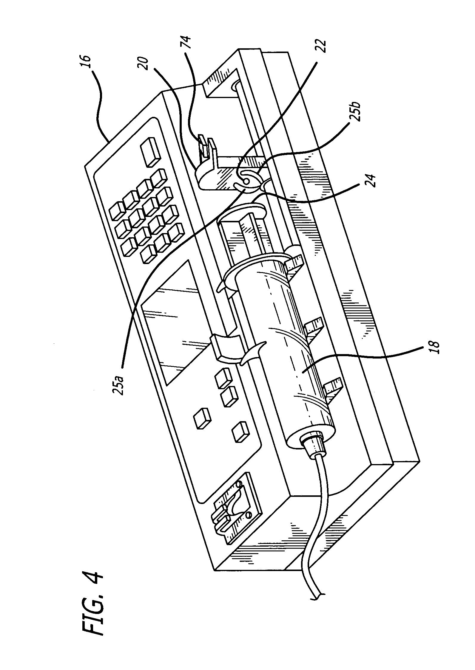
[0039]Referring now to the exemplary drawings wherein like reference numerals designate like or corresponding elements among the several views there is shown in FIG. 4 a syringe pump 16 having a syringe 18 mounted in the pump. A plunger driver 20 not yet engaged with the syringe plunger flange 24 includes a plunger sensor button 22 which is used to detect the presence of a syringe plunger 24 pressed against the plunger driver. During fluid infusion, the plunger driver presses against the syringe plunger. In FIG. 4, the plunger driver is retracted rearward away from the syringe plunger so that the plunger sensor button may be seen. The syringe plunger driver also includes two rotating arms 25a and 25b in this embodiment that will capture the syringe plunger flange against the driver to prevent siphoning from the syringe.

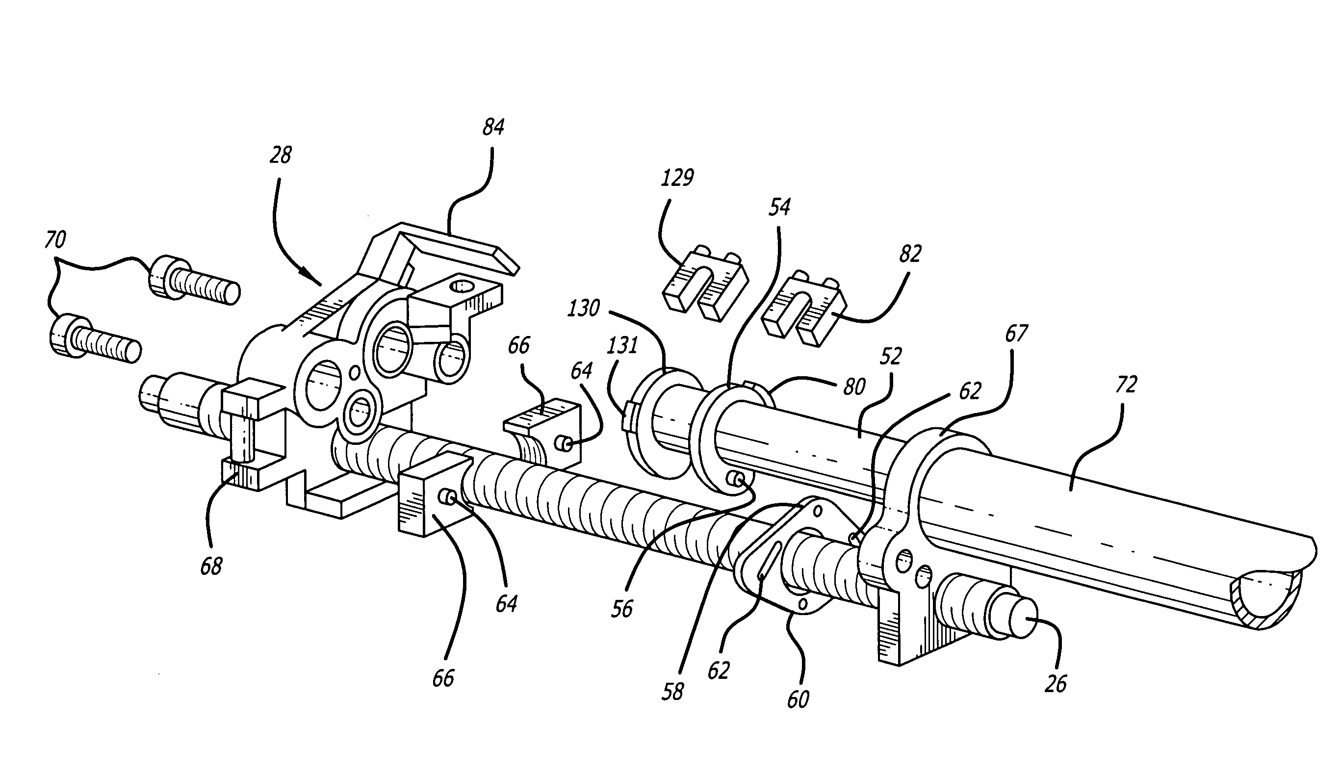
[0040]Referring now to FIG. 5, a lead screw 26 is in thread engagement with a moveable screw drive mechanism 28 that is coupled to the plunger driver 20. The screw dr...


PUM


Abstract

A system and method for automatically aligning the threads of a lead screw with the threads of a screw drive mechanism, the screw drive mechanism operating to translate the rotational motion of the lead screw into linear motion to expel the contents of a mounted syringe. The system comprises a driver position sensor for determining the position of the screw drive mechanism along the lead screw and a processor for receiving position signals from the driver position sensor, for determining a requisite rotation of the lead screw to ensure alignment of the two sets of threads, and for effectuating the requisite rotation of the lead screw to achieve that alignment. An automatic calibration routine is included that checks for variances in calibration of the system and if found, updates a conversion factor to restore accuracy. Various sensors are used to monitor the operation of components.

Description

FIELD OF THE INVENTION[0001]The invention is related generally to screw drive mechanisms, and more particularly, to an engagement system and method for engaging a driver with a lead screw.BACKGROUND OF THE INVENTION[0002]The infusion of fluids such as parenteral fluids into the human body is accomplished in many cases by means of a syringe pump having a lead screw on which a screw drive mechanism is mounted. Rotation of the lead screw is translated into linear motion by the screw drive mechanism. The linear motion is transmitted to a syringe plunger by a plunger driver that is typically rigidly connected to the screw drive mechanism. To facilitate replacement of an empty syringe, split nuts or half nuts are used as part of the screw drive mechanism in some syringe pumps for easy and rapid repositioning of the screw drive mechanism and plunger driver on the lead screw to engage the syringe plunger of a full syringe with the plunger driver. An activating lever or other mechanical inte...

Claims


Application Information

Patent Timeline
Patent Type & Authority Patents(United States)
IPC IPC(8): F16H1/18
CPCA61M5/1456F16H25/2025A61M2005/14573A61M2205/52Y10T74/1406Y10T74/19735Y10T74/19902Y10T74/1974Y10T74/19805
Inventor SIEFERT, ROBERT J.
Owner CAREFUSION 303 INC
Why Eureka
Try Eureka