Print system and print system control method

a printing system and control method technology, applied in the direction of digital output to print units, electric controllers, instruments, etc., can solve the problems of imposing restrictions on the printing operation of printers, printers cannot continue printing operations, and reach preset values

Inactive Publication Date: 2009-06-09
SEIKO EPSON CORP
View PDF11 Cites 67 Cited by
  • Summary
  • Abstract
  • Description
  • Claims
  • Application Information

AI Technical Summary

Benefits of technology

[0006]The object of the present invention is to provide a print system and a corresponding print system control method that prevent the management server from suffering significant losses in case of failed connection of the print system with

Problems solved by technology

Failed establishment of connection with the management server, on the other hand, causes the count to reach the preset value and imposes restrictions on the printing

Method used


Image

  • Print system and print system control method
  • Print system and print system control method
  • Print system and print system control method

Examples


first embodiment

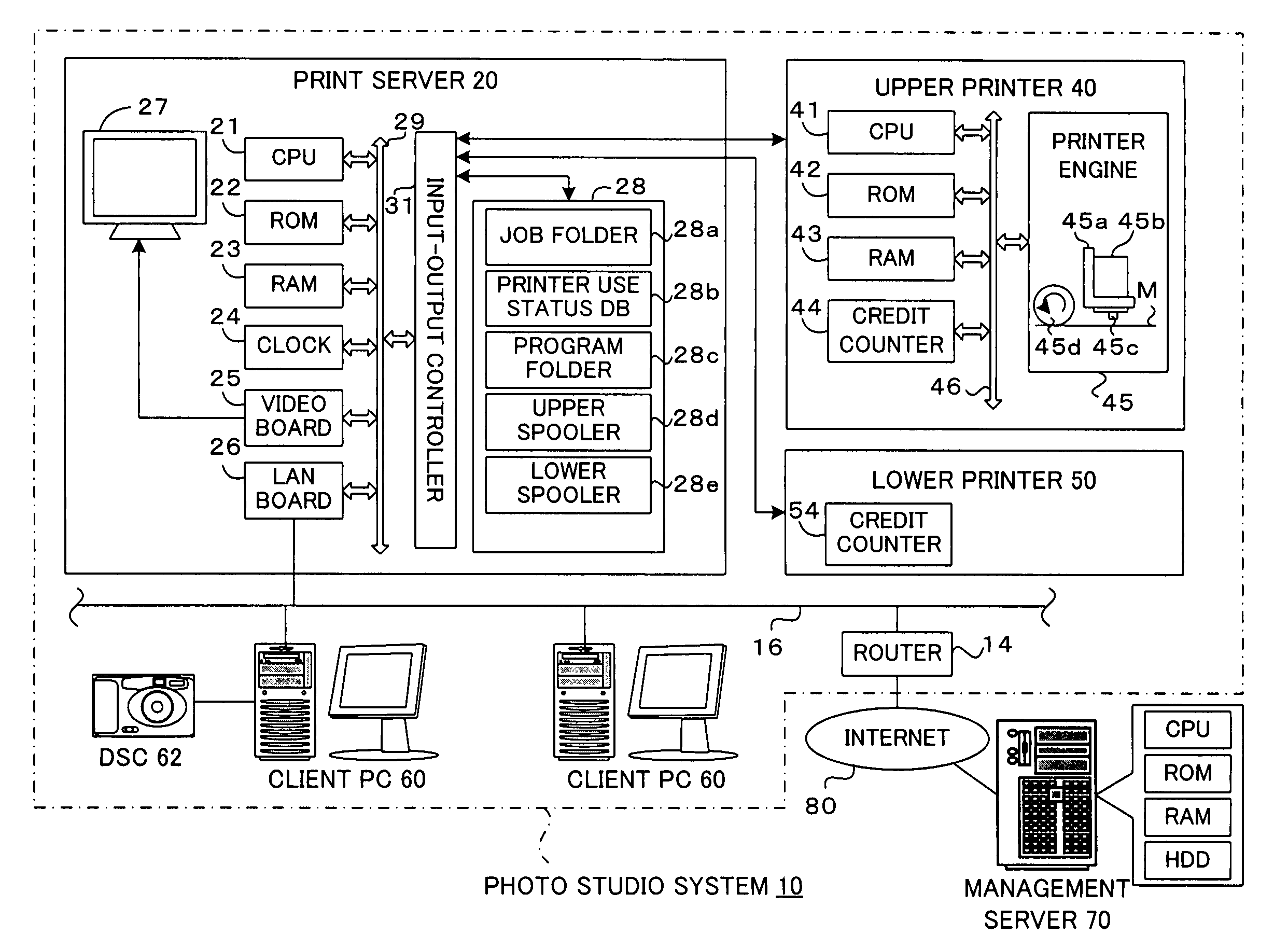
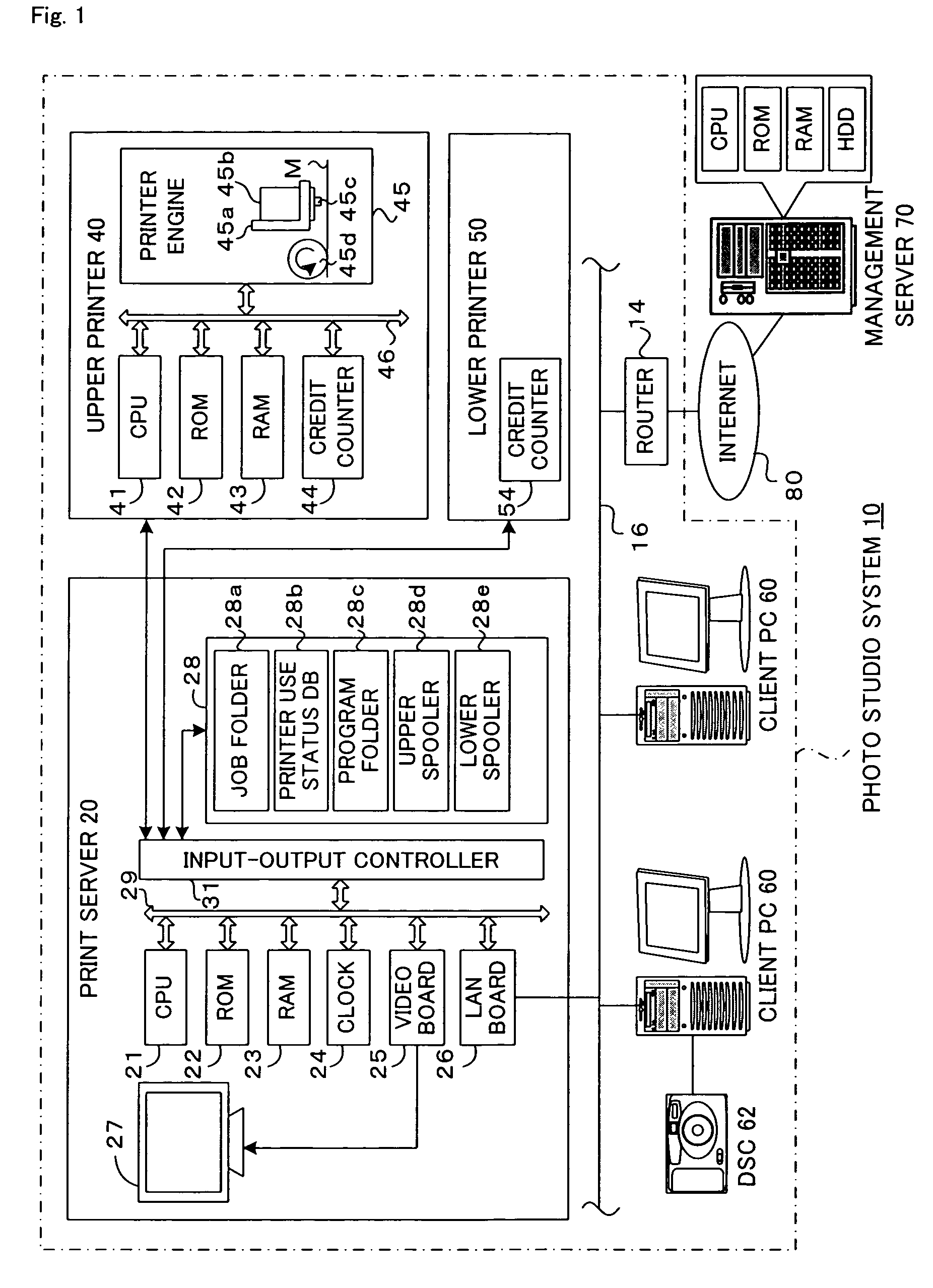
[0057]FIG. 1 schematically illustrates the configuration of a photo studio system 10 in a first embodiment of the invention. As illustrated in FIG. 1, the photo studio system 10 of the first embodiment includes a print server 20 that communicates with a management server 70 via the Internet 80 as a telecommunication line, multiple client PCs 60 that output print jobs to the print server 20, and two printers 40 and 50 that receive print jobs allocated by the print server 20. The two printers 40 and 50 and the print server 20 are placed in an identical casing. In the casing, the printer 40 is located on an upper step and the printer 50 is located on a lower step. In the description below, the printers 40 and 50 may thus be referred to as the upper printer 40 and the lower printer 50. The symbol ‘PC’ represents a personal computer.

[0058]The print server 20 has a CPU 21 that executes diverse operations and computations, a ROM 22 that stores a group of programs executed to, for example, ...

second embodiment

[0089]The structure and the operations of a second embodiment are similar to those of the first embodiment, except a printer verification routine. The following description focuses on such differences from the first embodiment.

[0090]In the second embodiment, a verification routine shown in the flowchart of FIG. 13 is executed at step S405 in the log transmission routine of FIG. 6. When this printer verification routine starts, the CPU 21 of the print server 20 executes the processing of steps S510 through S540, which is identical with that of the first embodiment discussed above with reference to the flowchart of FIG. 7. At step S540, the CPU 21 determines whether the calculated ratio of the actual number of printing operations by the printer 40 to the total number of printed sheets by the printer 40 is within a preset allowable range. When the calculated ratio is within the preset allowable range at step S540, the CPU 21 determines that the current working status of the printer 40 ...


PUM


Abstract

In photo studio system 10, a count which represents a number of printing operations with regard to each of the printer 40 and 50 is reset to zero in response to successful establishment of connection of a print server 20 with the management server 70. The printer 40 and 50 are allowed to continuously carry out printing operations as long as the count is reset to zero before reaching the preset value. On the other hand, failed establishment of connection with the management server 70 causes the count to reach the preset value and imposes restrictions on the printing operations with regard to each of the printer 40 and 50. Each of the printers is not allowed to continue printing operations over a long time period in the state of disconnection from the management server. This arrangement desirably prevents the management server from suffering significant losses.

Description

BACKGROUND OF THE INVENTION[0001]1. Field of the Invention[0002]The present invention relates to a print system that is capable of sending a status of a printer to a management server, which manages the status of the printer, via a telecommunication line, and a corresponding print system control method.[0003]2. Description of the Prior Art[0004]A known print system includes a print server that sends a status of each printer to a management server, which manages the status of the printer, via a network and receives print jobs from client computers, and two printers that are connected with the print server and receive allocation of print jobs by the print server (for example, Patent Laid-Open Gazette No. 2003-44255). This print system is located in each of multiple photo studios. The management server receives the statuses of printers from a print server of each print system located in each of the multiple photo studios and sets accounting to charge fees to the photo studio according ...

Claims


Application Information

Patent Timeline
IPC IPC(8): G06F15/00G05B11/01H04N1/00
CPCH04N1/00132H04N1/00188H04N1/00244H04N1/00832H04N1/00925H04N1/00204
Inventor TAKABAYASHI, NOBUHISASHIMADA, MIKIYA
Owner SEIKO EPSON CORP
Why Eureka
Try Eureka