Variable optical attenuator and ranging apparatus using the same

a technology of variable optical attenuator and ranging apparatus, which is applied in the direction of distance measurement, instruments, and using reradiation, can solve the problem of difficulty in rapid switching of density

Inactive Publication Date: 2009-06-09
KK TOPCON
View PDF10 Cites 3 Cited by
  • Summary
  • Abstract
  • Description
  • Claims
  • Application Information

AI Technical Summary

Problems solved by technology

However, since the above-mentioned density filter having the density gradient is required to have a large size and to be rotated by the motor, there is a problem in that it is difficult to rapidly switch the density.

Method used


Image

  • Variable optical attenuator and ranging apparatus using the same
  • Variable optical attenuator and ranging apparatus using the same
  • Variable optical attenuator and ranging apparatus using the same

Examples


example 1

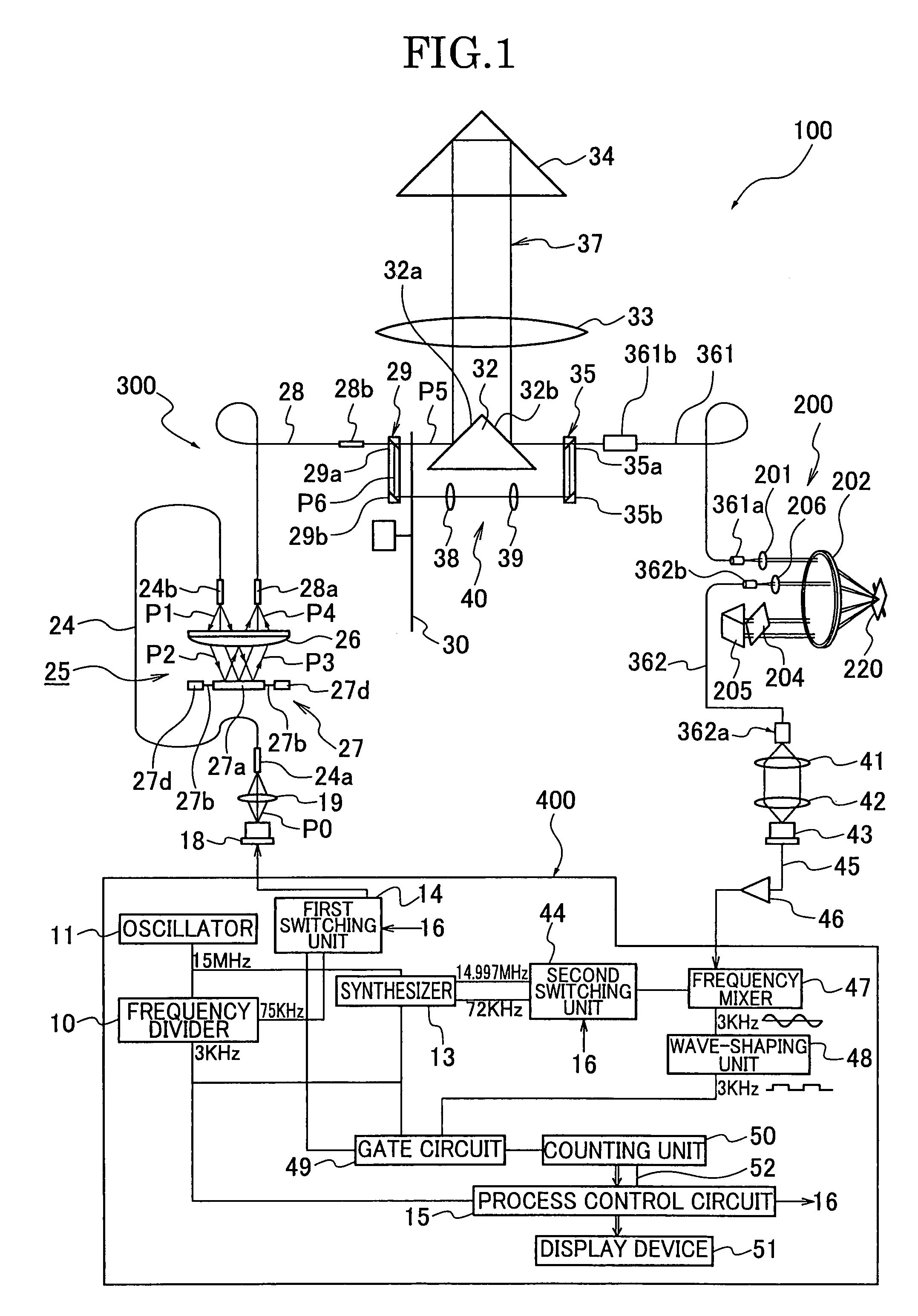
[0021]FIG. 1 shows a first example of a ranging apparatus 100 using a variable optical attenuator 200 according to the present invention. The ranging apparatus 100 has a semiconductor laser 18 as a light source which is controlled by a control device 400. A subject is irradiated with laser light emitted from the semiconductor laser 18 via a mixing device 300, and the light reflected from the subject is detected by a light-receiving portion, for example, a light-receiving element 43 to measure a distance to the subject.

[0022]The mixing device 300 includes a light-guiding optical fiber 24, a collimating lens 26, a reflection oscillating device 25, and a light-mixing optical fiber. The optical fibers 24, 28 have input ends 24a, 28a and output ends 24b, 28b, respectively. A diameter of the optical fiber 28 is, for example, 300 μm.

[0023]The semiconductor laser 18 is driven by an output signal from a first switching portion 14 (mentioned below) of the control device 400 to emit laser ligh...

embodiment 2

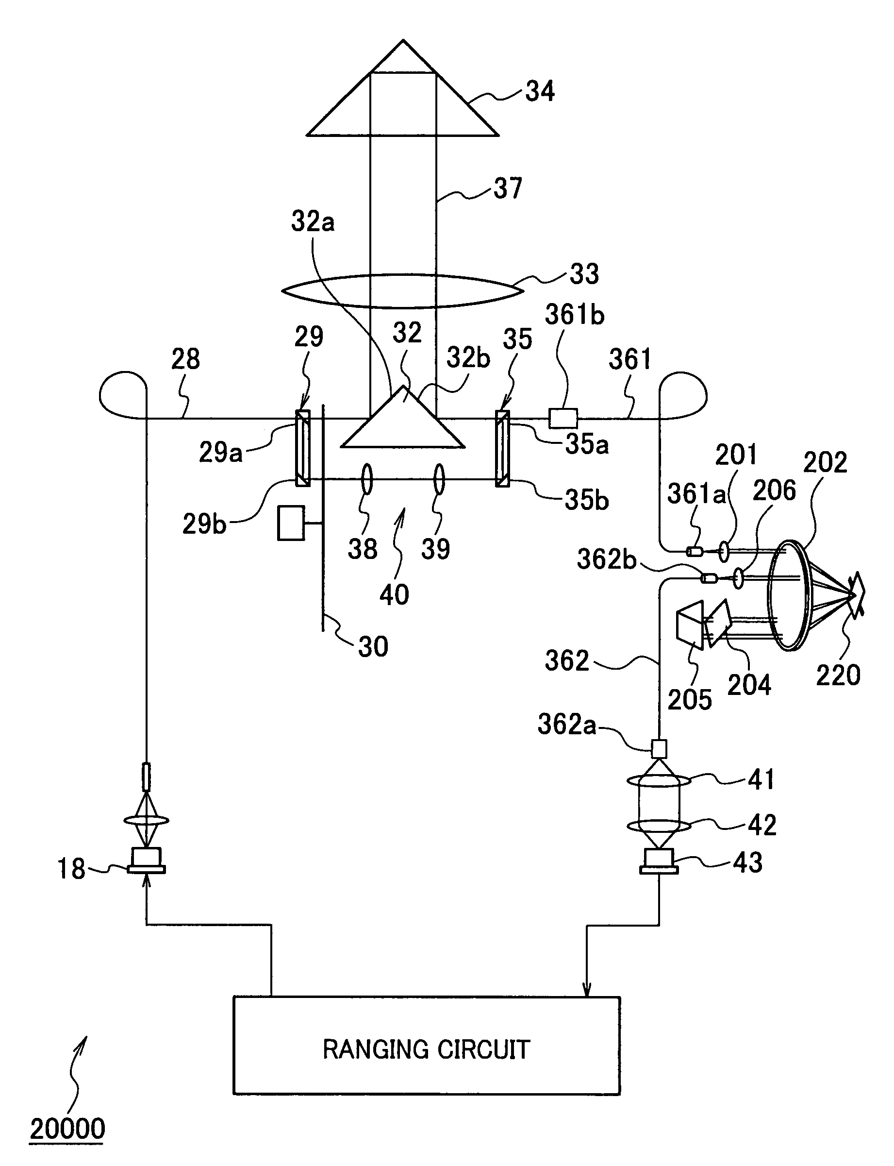
[0070]FIG. 8 shows a ranging apparatus 20000 of a second embodiment according to the present invention. The ranging apparatus 20000 is the same as that of the first embodiment except that the mixing device included in the ranging apparatus of the first embodiment is omitted.

[0071]According to the embodiment of the present invention, since the mirror is tilted to change the light-transmitting position of the laser light on the density filter, the high-speed switchings of the light power can be achieved.


PUM

PropertyMeasurementUnit
diameteraaaaaaaaaa
diameteraaaaaaaaaa
frequencyaaaaaaaaaa

Abstract

A variable optical attenuator for adjusting a power of light which is output from an output end of a first optical fiber and is to be led to an input end of a second optical fiber, includes a reflection member which reflects the light output from the output end of the first optical fiber, a density filter which transmits the light reflected from the reflection member and controls the power of the light which is transmitted by the density filter depending on a light-transmitting position on the density filter, and an optical member which reflects the light transmitted by the density filter to lead the light to the reflection member. The reflection member is disposed tiltably, the power of the light transmitted by the density filter attenuates along a direction in which the light-transmitting position is changed, and the light-transmitting position of the light is changed by tilting the reflection member.

Description

CROSS-REFERENCE TO RELATED APPLICATIONS[0001]This application is based on and claims priority from Japanese Patent Application Nos. 2006-215526, filed on Aug. 8, 2006, and 2006-294219, filed on Oct. 30, 2006, the disclosure of which is incorporated herein by reference in its entirety.BACKGROUND OF THE INVENTION[0002]1. Field of the Invention[0003]The present invention relates to a variable optical attenuator and a ranging apparatus using the variable optical attenuator.[0004]2. Description of the Related Art[0005]A ranging apparatus for measuring a distance by irradiating light to a subject and receiving the light reflected from the subject has been known (Japanese Patent Laid-Open Publication Number 2001-162517).[0006]The ranging apparatus has a variable optical attenuator having a density filter which adjusts a light power of an internal reference-light path and an external measurement-light path. The density filter has a density gradient in a rotational direction, and a density, ...

Claims


Application Information

Patent Timeline
Patent Type & Authority Patents(United States)
IPC IPC(8): G02B6/26C01C3/08G01C3/00G02B6/00
CPCG01S7/481G01S17/08G02B6/266G01S7/4868
Inventor FUJINO, MAKOTOKAWASHIMA, HIROYUKI
Owner KK TOPCON
Why Eureka
Try Eureka