Microelectromechanical system (MEMS) variable optical attenuator

a microelectromechanical system and variable technology, applied in the field of optical attenuators, can solve the problems of not being able to meet the need for a small sized mems optical variable attenuator, unable to adopt a conventional mems variable optical attenuator, and difficult to achieve an adequate attenuation level of incident light beams, etc., and achieve the effect of large displacemen

Inactive Publication Date: 2005-05-31
SAMSUNG ELECTRO MECHANICS CO LTD
View PDF19 Cites 32 Cited by
  • Summary
  • Abstract
  • Description
  • Claims
  • Application Information

AI Technical Summary

Benefits of technology

[0016]Therefore, the present invention has been made in view of the above problems, and it is an object of the present invention to provide an MEMS variable optical attenuator provided with an actuator capable of providing an optical shutter with a large displacement

Problems solved by technology

However, even though the optical collimator has such advantages as described above, it cannot be adopted in a conventional MEMS variable optical attenuator due to its large mode field diameter (MFD).
However, in the case of using an optical collimator, a MFD of the optical fiber increases to 100 μm, or to 200-300 μm under certain circumstances, so that it is difficu

Method used


Image

  • Microelectromechanical system (MEMS) variable optical attenuator
  • Microelectromechanical system (MEMS) variable optical attenuator
  • Microelectromechanical system (MEMS) variable optical attenuator

Examples


first embodiment

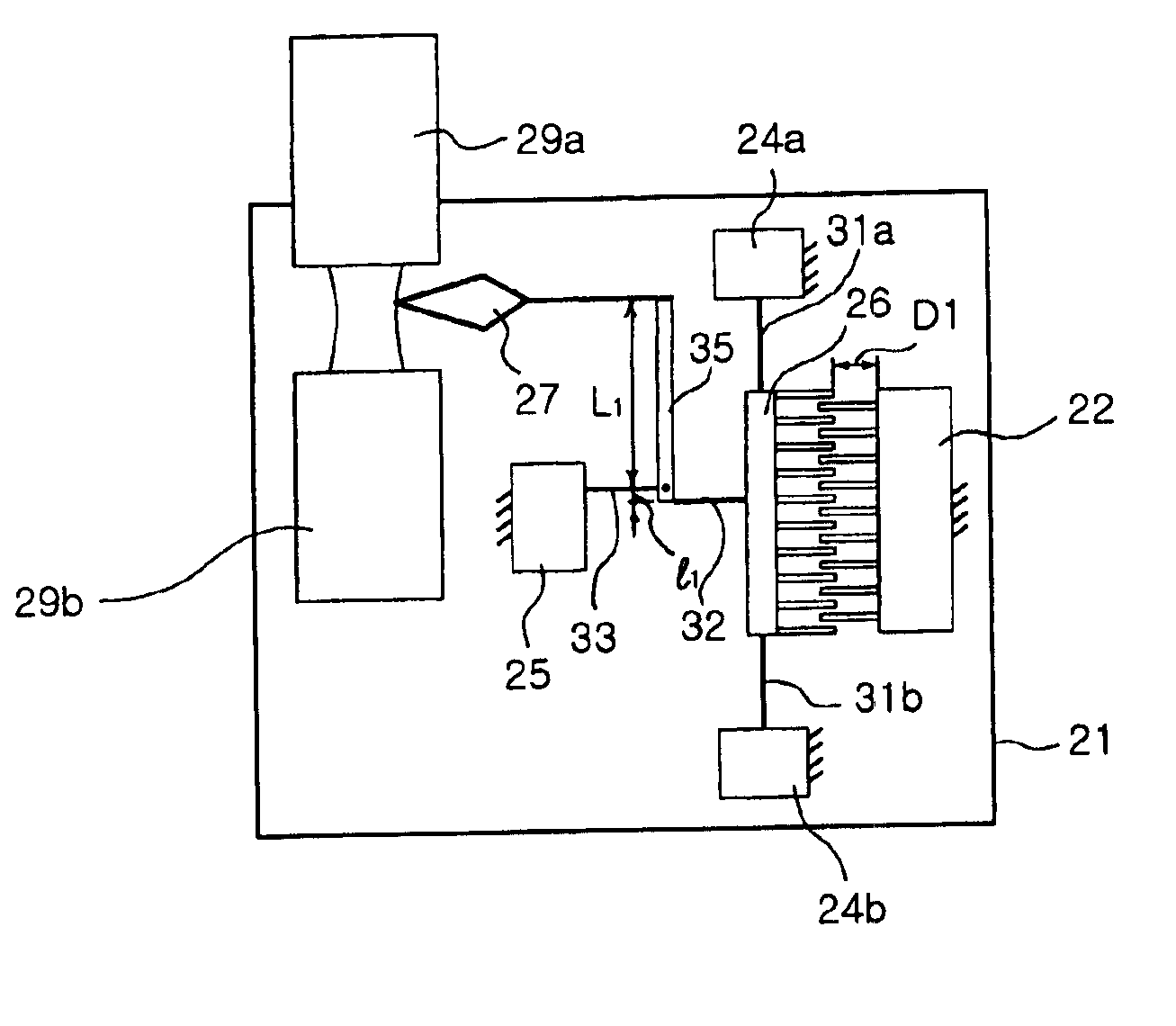
[0032]FIG. 2 illustrates a plan view of an MEMS variable optical attenuator in accordance with the present invention.

[0033]Referring to FIG. 2, an MEMS variable optical attenuator in accordance with a first embodiment of the present invention includes a substrate 21 having a pair of optical fibers with an optical signal transmitting end 20 and an optical signal receiving end 30, respectively, an electrostatic actuator comprised of a driving electrode 22, ground electrodes 24a, 24b and a movable mass 12, a lever structure 35 for amplifying a driving stroke of the actuator so as for an optical shutter to be displaced by a displacement distance greater than the driving stroke of the actuator, and an optical shutter 27 coupled to the lever structure 35.

[0034]The driving electrodes 12a, 12b and the ground electrode 14 are structures (hatched portion) formed over the substrate 11 and supported by an oxide layer (not shown). The movable mass 26 is connected to the ground electrodes 24a, 24...

second embodiment

[0046]Referring to FIG. 3, an MEMS variable optical attenuator of the present invention includes a substrate having optical fibers with a transmitting end 129a and a receiving end 129b, respectively, thereon, an electrostatic actuator comprised of a driving electrode 122, ground electrodes 124a, 124b and a movable mass 126, two lever structures 135a, 135b which are bilaterally symmetrically arranged, and an optical shutter 127 coupled to the lever structures 135a, 135b.

[0047]The driving electrode 122 and the ground electrodes 124a, 124b are supported by an oxide layer 128 and fixed on the substrate 121 in similar manner to the MEMS variable optical attenuator shown in FIG. 2. The movable mass 126 is connected to the ground electrodes 124a, 124b arranged at both sides thereof by first elastic structures 131a, 131b, respectively, and suspended over the substrate 121. The first elastic structures 131a, 131b act as linear springs, thereby enabling the movable mass 126 to move along a p...

third embodiment

[0062]The MEMS variable optical attenuator in accordance with the present invention includes a substrate 161 having a pair of optical fibers with an optical signal transmitting end 169a and an optical signal receiving end 169b, respectively, an elastic actuator comprised of a driving electrode 162, ground electrodes 164a, 164b and a movable mass 166, two lever structures 175a, 175b bilaterally symmetrically arranged, and an optical shutter connected to the lever structures 175a, 175b. The driving electrode 162 is fixed on the substrate 161 and supported by an oxide layer 168 formed on the substrate 161. The movable mass 166 are connected to the ground electrodes 164a, 164b arranged at both sides thereof by first elastic structures 171a, 171b and suspended over the substrate 161. Here, the first elastic structures 171a, 171b act as a linear spring defining a driving stroke of the movable mass, thereby enabling the movable mass 166 to move linearly by the driving stroke.

[0063]The firs...


PUM


Abstract

Disclosed is an MEMS variable optical attenuator comprising a substrate having a planar surface, optical fibers having an optical signal transmitting end and an optical signal receiving end, respectively, coaxially arranged on the substrate, a micro-electric actuator arranged on the substrate for providing a driving stroke along a direction perpendicular to an optical axis of the optical beam, at least one lever structure arranged on the substrate for receiving the driving stroke of the micro-electric actuator at a first end thereof and transferring an amplified displacement distance to an optical shutter through a second end thereof, an optical shutter arranged on the substrate and connected to the second end of the lever structure so as to be moved by the amplified displacement distance, thereby being displaced to an attenuation position of the optical beam.

Description

BACKGROUND OF THE INVENTION[0001]1. Field of the Invention[0002]The present invention relates to an optical attenuator that uses an element of a micro-electro-mechanical system (MEMS) device, and more particularly to an MEMS variable optical attenuator capable of amplifying a displacement distance of an optical shutter so that the displacement distance is compatible with a large mode field diameter (MFD) of an optical signal transmitting end or an optical signal receiving end of an optical fiber.[0003]2. Description of the Related Art[0004]An optical attenuator is an optical component for use in optical telecommunication networks. The optical attenuator includes a pair of optical waveguides having an optical signal transmitting end and an optical signal receiving end, respectively, and attenuates an optical power of an optical beam passing out the transmitting end of the optical waveguide and entering the receiving end of the optical waveguide by causing insertion loss of the optica...

Claims


Application Information

Patent Timeline
IPC IPC(8): G02B6/26G02B6/35G02B6/00B81B3/00G02B26/02H02N1/00
CPCG02B6/266G02B6/353G02B6/3584G02B6/3594G02B6/357G02B6/3552G02B26/02
Inventor HONG, YOON SHIKYOON, SANG KEEHONG, SUK KEELEE, YOUNG GYUJUNG, SUNG CHEONLEE, JUNG HYUN
Owner SAMSUNG ELECTRO MECHANICS CO LTD
Why Eureka
Try Eureka