Inclination angle adjusting mechanism for image pickup device

a technology of inclination angle and adjustment mechanism, which is applied in the direction of printers, photosensitive materials, camera focusing arrangement, etc., can solve the problem that the range of tightening of each adjustment screw cannot be fully utilized to the limit as an effective effect, and achieve the effect of convenient and reliable manner

Inactive Publication Date: 2009-06-09
HOYA CORP
View PDF24 Cites 8 Cited by
  • Summary
  • Abstract
  • Description
  • Claims
  • Application Information

AI Technical Summary

Benefits of technology

[0005]The present invention provides an inclination angle adjusting mechanism with which the inclination angle of an image pickup device can be adjusted in an easy and reliable manner.
[0011]It is desirable for the inclination angle adjusting mechanism to be incorporated in an imaging stabilizer which moves the image pickup device in a plane orthogonal to an optical axis to counteract image shake of an object image formed on an imaging surface of the image pickup device.
[0019]According to the present invention, an inclination angle adjusting mechanism in which the range of tightening of each adjustment screw can be fully utilized to the limit as an effective range of adjustment of the inclination angle of the image pickup device and with which the inclination angle of an image pickup device can be adjusted in an easy and reliable manner is achieved.

Problems solved by technology

However, such a known inclination angle adjusting mechanism is constructed so that the image pickup device is held between screw bearing seats and the heads of the adjustment screws to fix the image pickup device mounting member relative to the reference member in a state where each adjustment screw is screwed into the reference member to the maximum; and accordingly, the range of tightening of each adjustment screw cannot be fully utilized to the limit as an effective range of adjustment of the inclination angle of the image pickup device.

Method used


Image

  • Inclination angle adjusting mechanism for image pickup device
  • Inclination angle adjusting mechanism for image pickup device
  • Inclination angle adjusting mechanism for image pickup device

Examples


Embodiment Construction

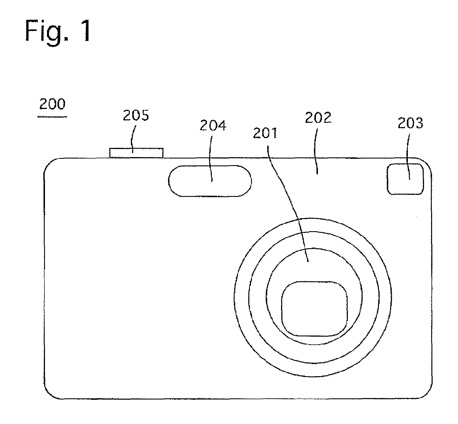
[0061]FIG. 1 shows an outward appearance of a digital camera 200 which incorporates an inclination angle adjusting mechanism for changing the inclination angle of an image pickup device according to the present invention. The digital camera 200 is provided on the front of a camera body 202 thereof with a zoom lens (zoom Lens barrel) 201, an optical view finder 203 and a flash 204, and is provided on the top of the camera body 202 with a shutter button 205.

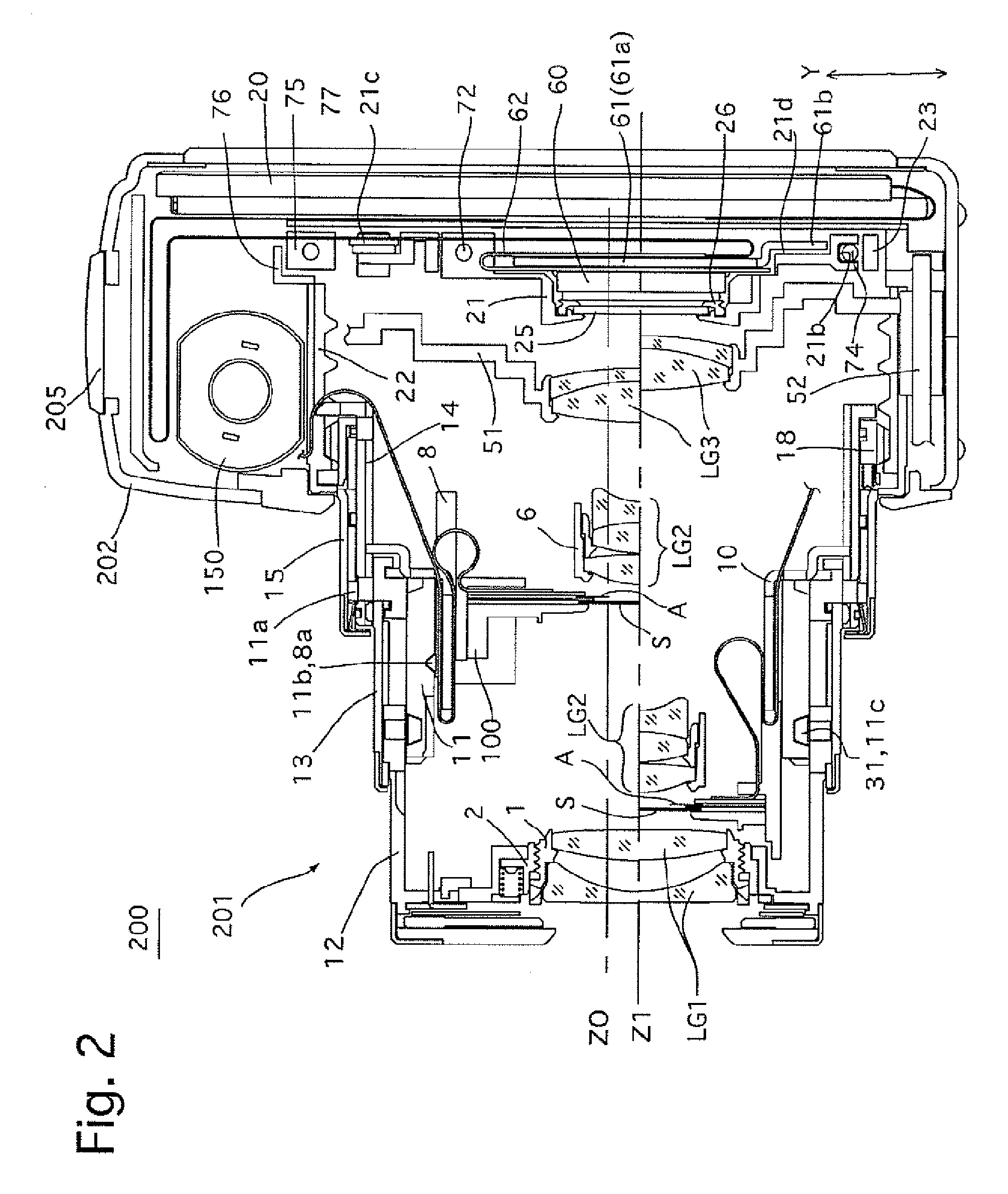
[0062]The zoom lens 201 of the digital camera 200, longitudinal sectional views of which are shown in FIGS. 2 and 3, is driven to advance toward the object side (leftward as viewed in FIGS. 2 and 3) from the camera body 202 as shown in FIG. 2 during a photographing operation. When photography is not being carried out, the digital camera 200 moves from a ready-to-photograph state shown in FIG. 2 to a fully-retracted state shown in FIG. 3 in which the zoom lens 201 is accommodated (fully retracted) in the camera body 202 as shown in ...


PUM


Abstract

An inclination angle adjusting mechanism includes a mounting plate to which an image pickup device is mounted; a reference member holding the mounting plate; through-holes formed in the mounting plate; screw bearing seats projecting from the reference member; adjustment screws screwed into female screw holes formed in the screw bearing seats, respectively, and head portions of the adjustment screws being in contact with the mounting plate; and a biasing device so as to bring the mounting plate into contact with back surfaces of the adjustment screws. Maximum tightening positions of the adjustment screws are defined by engagement of back surfaces of the head portions with ends of the screw bearing seats, wherein the mounting plate remains not in contact with the reference surface.

Description

BACKGROUND OF THE INVENTION[0001]1. Field of the Invention[0002]The present invention relates to an inclination angle adjusting mechanism for changing an angle (inclination angle) of an image pickup device provided in an imaging device such as a digital camera.[0003]2. Description of the Related Art[0004]Imaging devices such as digital cameras are generally provided with an inclination angle adjusting mechanism for changing the angle (inclination angle) of an image pickup device relative to an optical axis. This inclination angle can be adjusted by changing the balance among the tightening amounts of a plurality of adjustment screws. This type of inclination angle adjusting mechanism is known in the art as an inclination angle adjusting mechanism in which an image pickup device mounting member to which the image pickup device is mounted is biased in a direction away from a reference member into which the adjustment screws are screwed so that the position of the image pickup device m...

Claims


Application Information

Patent Timeline
Patent Type & Authority Patents(United States)
IPC IPC(8): G03B17/00G02B7/02H04N5/225G03B17/02G03B21/14G03B21/22G03D13/00
CPCG03B13/18
Inventor NOMURA, HIROSHISUZUKA, SHINYAENDO, KEN
Owner HOYA CORP
Why Eureka
Try Eureka