
Flow control device

Inactive Publication Date: 2009-06-16
SCHLUMBERGER TECH CORP
View PDF10 Cites 6 Cited by
  • Summary
  • Abstract
  • Description
  • Claims
  • Application Information

AI Technical Summary

Benefits of technology

[0012]More precisely, the invention provides a flow control device in which the portion of the production tube is provided with means of protection against wear by erosion acting not only around the contours of the openings but also at the inner surface of the openings, the protection means easily being adapted to the portion of the tube regardless of the required geometric shape of these openings.
[0023]According to a preferred embodiment of this invention, the inner stiffener of each add-on sector is provided with a seal that fits on the internal wall of the through orifice in which it is located. In this manner, fluid cannot pass between the through orifices and the inner stiffeners, which has the effect of significantly increasing the precision of the flow control, and eliminating any pressure loss between these different elements. Furthermore, the seals provided enable the add-on sectors to be firmly fixed in the through orifices, considerably reducing vibrations of these sectors, and shocks between the sectors and the inner surface of the through orifices.

Problems solved by technology

However, one major problem with this type of flow control device is that of erosion of the tube around the holes due to the presence of solids (sand) in the produced fluids, to the extent that the valve can lose the ability to control flow effectively and ultimately to fail completely.
Although the entire production tube may be degraded due to wear caused by passage of the fluid, certain localized parts are subject to more severe wear and deterioration.
In particular, this is the case at the contours around holes through which fluid passes, which are subject to wear and damage causing a malfunction of the flow control device.
Wear of these contours by erosion may be harmful for the precision of the control device, since these imprecisions can make it possible for flow variations to arise independently of variations caused by control of the relative position of the closing sleeve and the passage holes.
Although the technological solution proposed and mentioned above has led to relative improvements to the life of the portion of the production tube provided with the protective envelope, it was quickly realized that this technique provided insufficient protection for a device with suitable resistance to wear by erosion.
The simple fact of providing a protective envelope around the outer surface of the portion of the production tube does not provide any protection against wear by erosion of the inner surface of the fluid passage holes.
Experiments carried out have shown that this weakness can also cause equipment deterioration due to erosion, and thus encourage the appearance of inaccuracies in the fluid flow control.
Nevertheless, force fitting of this assembly is not easy for all types of protection inserts, and particularly for inserts with a complex geometrical shape.
Consequently, when the shapes of passage holes are complex, techniques known in prior art do not propose any high performance means of protecting the inside of fluid passage holes against wear by erosion.

Method used


Image

  • Flow control device
  • Flow control device
  • Flow control device

Examples


Embodiment Construction

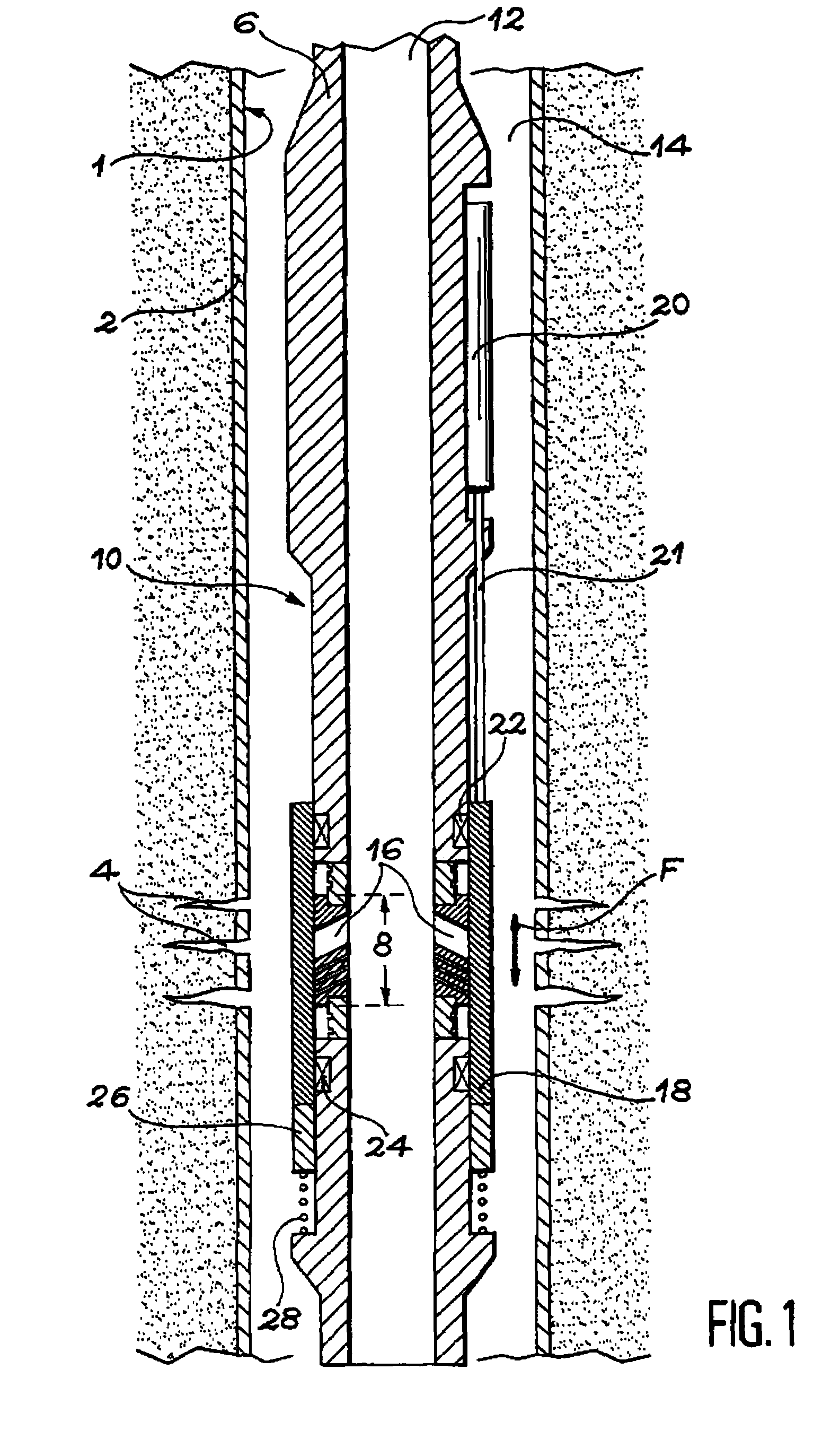
[0032]FIG. 1 shows an oil well in production, in which only a lower region is shown. This bottom region may be oriented vertically, as shown, horizontally inclined. If the flow control device is placed in a horizontal or inclined region of the well, expressions such as “downwards” and “upwards” used in the following description should be taken to mean “in the direction away from the surface” and “in the direction towards the surface” respectively.

[0033]The walls of the well 1 are reinforced by a casing 2. In the region of the well shown in FIG. 1, the casing 2 is provided with perforations 4 to provide a communication path between the inside of the well 1 and the underground formation having fluids therein (not shown).

[0034]To enable the fluid to be transferred to the surface, a production tube 6 is inserted coaxially over the full height of the well 1. The protection tube 6 is composed of a number of tube segments connected end to end. Part of the flow control device 10 is made on ...


PUM


Abstract

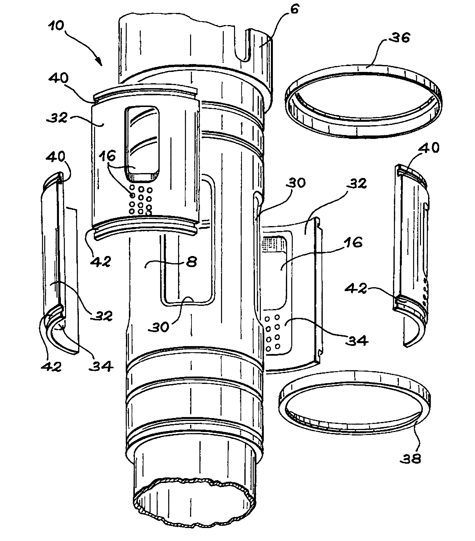
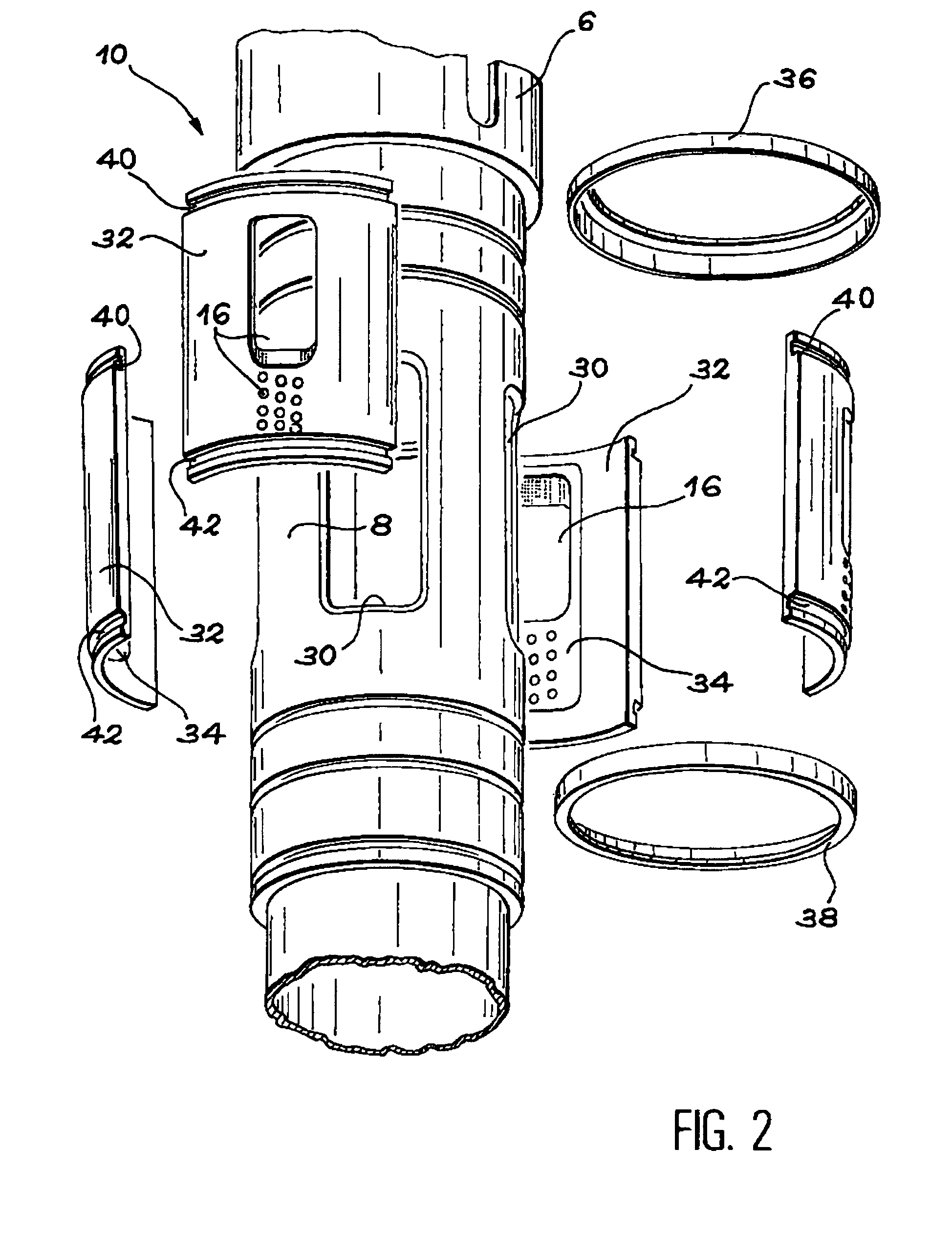
The invention relates to a device for control of the flow through a production tube placed in an oil well. The device comprising a portion of the production tube provided with through orifices and protection equipment for providing resistance to wear by erosion. The protection equipment comprises several add-on sectors assembled around the portion of the tube. Each add-on sector provided with an associated inner stiffener penetrating into the portion of the production tube through at least one through orifice. At least one of the add-on sectors provided with at least one opening extending through the sector and its associated inner stiffener.

Description

TECHNICAL FIELD[0001]The invention is related to a device designed to permit the flow of a fluid through a production tube in an oil well or the like.[0002]Such devices may be used in a well to optimize production or injection of fluids from or into the well as a function of time. It is particularly applicable to wells in which the fluid enters the well at a number of different locations along its length.[0003]Various implementations of flow control devices or valves have already been proposed in the domain of oil wells or the like.STATE OF THE PRIOR ART[0004]One such device is described in document FR-A-2 790 509, comprises holes formed in a production tube, and a closure sleeve installed on the outside of the production tube and free to slide in front of each hole formed so as to control the flow therethrough. In this manner, the fluid flow passing through the production tube is adjusted by controlling the closure sleeve which allows only a limited amount of fluid to pass therethr...

Claims


Application Information

Patent Timeline
IPC IPC(8): E21B34/00E21B21/10E21B34/06
CPCE21B21/103E21B34/06
Inventor CANTIN, GILLESTOURILLON, VINCENTGERGELE, VINCENT
Owner SCHLUMBERGER TECH CORP
Learn More