Mobile sleeve structure for maintaining spatial relationship between vertebrae

a mobile sleeve and spatial relationship technology, applied in the field of spinal implant systems, can solve the problems of not being able to maintain the desired spatial relationship, prone to misplacement, and not being able to accommodate the natural lordotic curvature of an individual patient's spinal column, so as to prevent the damage to the template, the adjustable sleeve, or the vertebra

Active Publication Date: 2009-06-16
RAPP LAWRENCE G
View PDF5 Cites 13 Cited by
  • Summary
  • Abstract
  • Description
  • Claims
  • Application Information

AI Technical Summary

Benefits of technology

[0014]In a further embodiment of the invention, a generally rectangular adjustable sleeve slidably connects the uppermost template and the lowermost template by means of the aforementioned posts and / or apertures through, the templates. It is an advantage of the invention that perfect placement of the adjustable sleeve is achieved because the posts extend generally perpendicular with respect to the midportion of the anterior vertebral body. The adjustable sleeve has a bottom sleeve portion that perpendicularly couples at a first end to the middle region of the lowermost template. A second end of the bottom sleeve portion extends upward toward the uppermost template. With respect to the distance between the anterior and posterior surfaces, the bottom sleeve portion will have a thickness at the first end that differs from that of its second end. In some embodiments of the invention, the thickness at the first end is about 1 mm and will increase to about 2 mm in the middle region and at second end of the bottom sleeve portion. The reason for the varying thickness is so that several adjustable sleeves can be stacked onto the posts of the lowermost template without any large protrusions in the lowermost template area. The thickness of the lowermost template is not limited to 1 mm and 2 mm since sleeves of various thicknesses will be needed depending on the needs of a particular surgical procedure.
[0015]In a further embodiment, the adjustable sleeve has a top sleeve portion with a first end that couples to post holes in the middle region of the uppermost template. The top sleeve portion also extends downward toward the bottom sleeve portion and terminates at a second end. With regard to thickness (i.e., the distance between the anterior and posterior surfaces), the top sleeve portion will have a different thickness at the first end than at the second end of the top sleeve portion. Illustratively, the thickness at the first end can be about 1 mm and will increase to about 2 mm as for the middle and second end of the top sleeve portion. The reason for the varying thickness is so that several adjustable sleeves can be stacked onto the posts of the uppermost template without any large protrusions in the uppermost template area. The thickness of the uppermost template is not limited to 1 mm and 2 mm since sleeves of various thicknesses will be needed depending on the needs of a particular surgical procedure. The second end of the top sleeve portion also has an opening to a hollow channel that extends upward toward the first end of the top sleeve portion. The second end of the bottom sleeve portion enters the bottom end of the top sleeve portion and is slidably disposed through the hollow channel.
[0016]The hollow channel affords mobility to the top third of the adjustable sleeve and allows the height of the mobile sleeve to adjust for post-operative subsidence of the vertebrae. The movement of the adjustable sleeve during subsidence enables the resulting load to be shared equally by all of the components of the mobile sleeve. Such distribution of the load increases the integrity of the mobile sleeve by preventing the damage to the templates, adjustable sleeve, or the vertebrae that may occur when the load is not equally distributed.
[0017]In order to control sliding movement between the top and lowermost templates, a tongue and groove mechanism can, in certain embodiments, be incorporated along the anterior surface of the adjustable sleeve. One or more tongues protrude from the anterior surface of the bottom sleeve portion that is disposed through the hollow channel, extending orthogonally outward from the anterior surface. One or more grooves are located on the anterior surface of the top sleeve portion and are arranged to extend completely through the anterior side of the top sleeve portion, whereby the tongues will extend into and slide freely within the grooves. In the practice of this embodiment, the grooves are of sufficient length to allow a top sleeve portion and a bottom sleeve portion to slide relative to each other and thereby accommodate subsidence of the vertebrae. However, the grooves will not be so long as to permit the bottom sleeve portion to become separated from the top sleeve portion.
[0018]The lowermost two thirds portion of the adjustable sleeve (i.e., the lower portion of the bottom sleeve portion) is formed of a solid material that can be bent with a plate bender so that the adjustable sleeve will correspond substantially to the curvature of the vertebral column. Although the adjustable sleeve is described herein as having a top third portion that can be adjusted for length and a bottom two thirds that are solid, different ratios are achievable depending upon the region to which the mobile sleeve is to be attached, or the particular needs of a patient.
[0019]In a further embodiment, a locking plate holds the adjustable sleeve and template together to allow the distribution of stress to all the parts of the mobile sleeve. Controlling the distribution of stress contributes to advantageous distribution of the load by ensuring that no one particular portion of the mobile sleeve is burdened excessively by the stress that is caused by the subsidence of the vertebrae. The locking plate in this embodiment has two or more post holes that are aligned and placed onto the two or more posts of the bottom or uppermost templates. In order to hold the locking plate in place, the post holes of the locking plate are configured to be secured onto the posts as the locking plate moves into place. In other embodiments, the posts of the uppermost template and the lowermost template are threaded so that a fastener, such as a nut, can be used to lock the locking plate in place.

Problems solved by technology

A problem with vertebral fusion procedures is that once the bone grafts are implanted they are prone to becoming misplace due to movement of the adjacent vertebrae.
It is a deficiency of the above system that plates of various heights must be prefabricated and made available during the procedure because the distance between respective pairs of vertebrae will vary along the length of the anterior cervical column.
Another problem with the known system is that the plates are only used between two vertebrae and cannot be used to maintain a desired spatial relationship between three or more vertebrae.
A problem with the known rod system is that it does not accommodate the natural lordotic curvature of an individual patient's spinal column as the lordotic curvature varies from patient to patient.

Method used


Image

  • Mobile sleeve structure for maintaining spatial relationship between vertebrae
  • Mobile sleeve structure for maintaining spatial relationship between vertebrae
  • Mobile sleeve structure for maintaining spatial relationship between vertebrae

Examples


Embodiment Construction

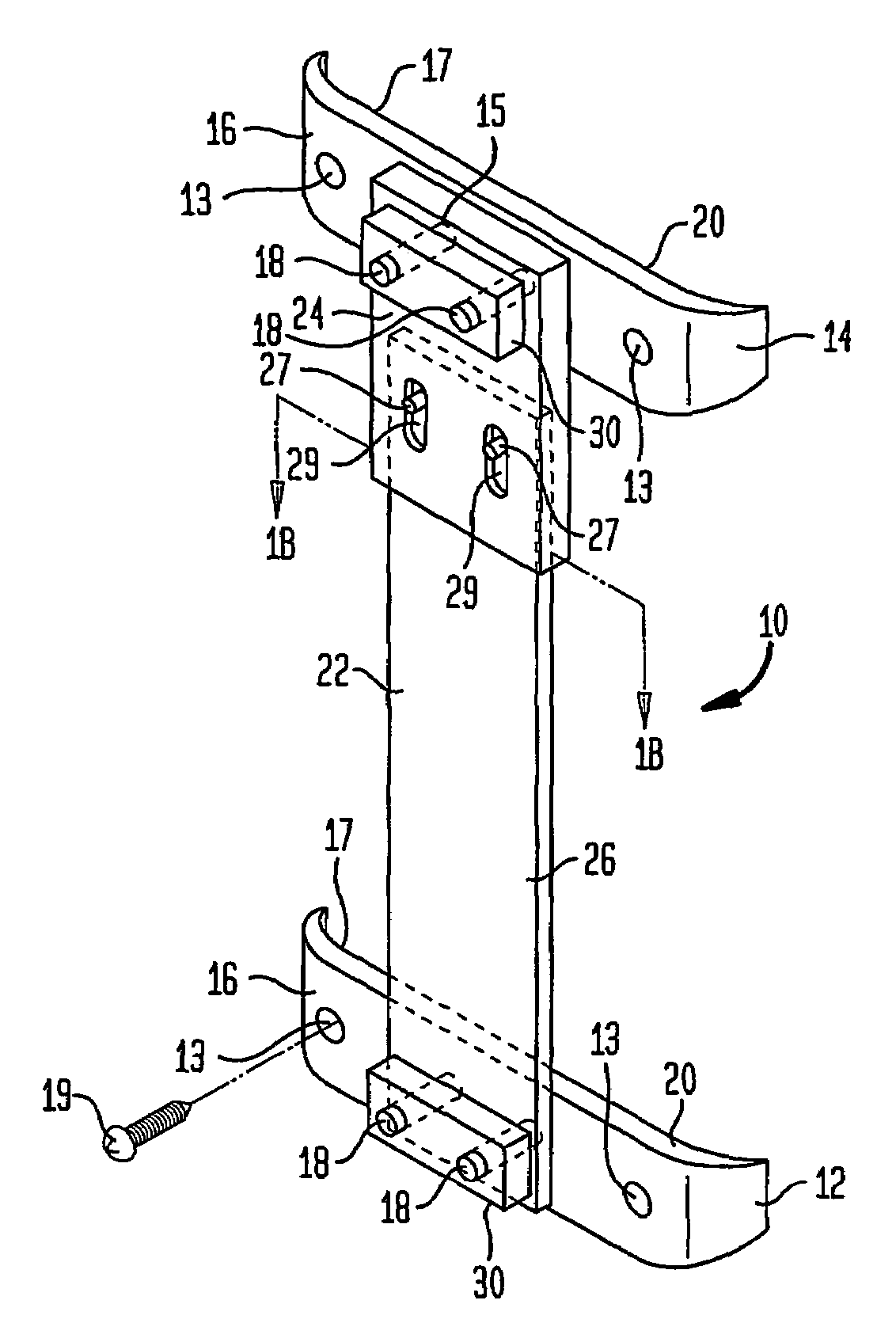
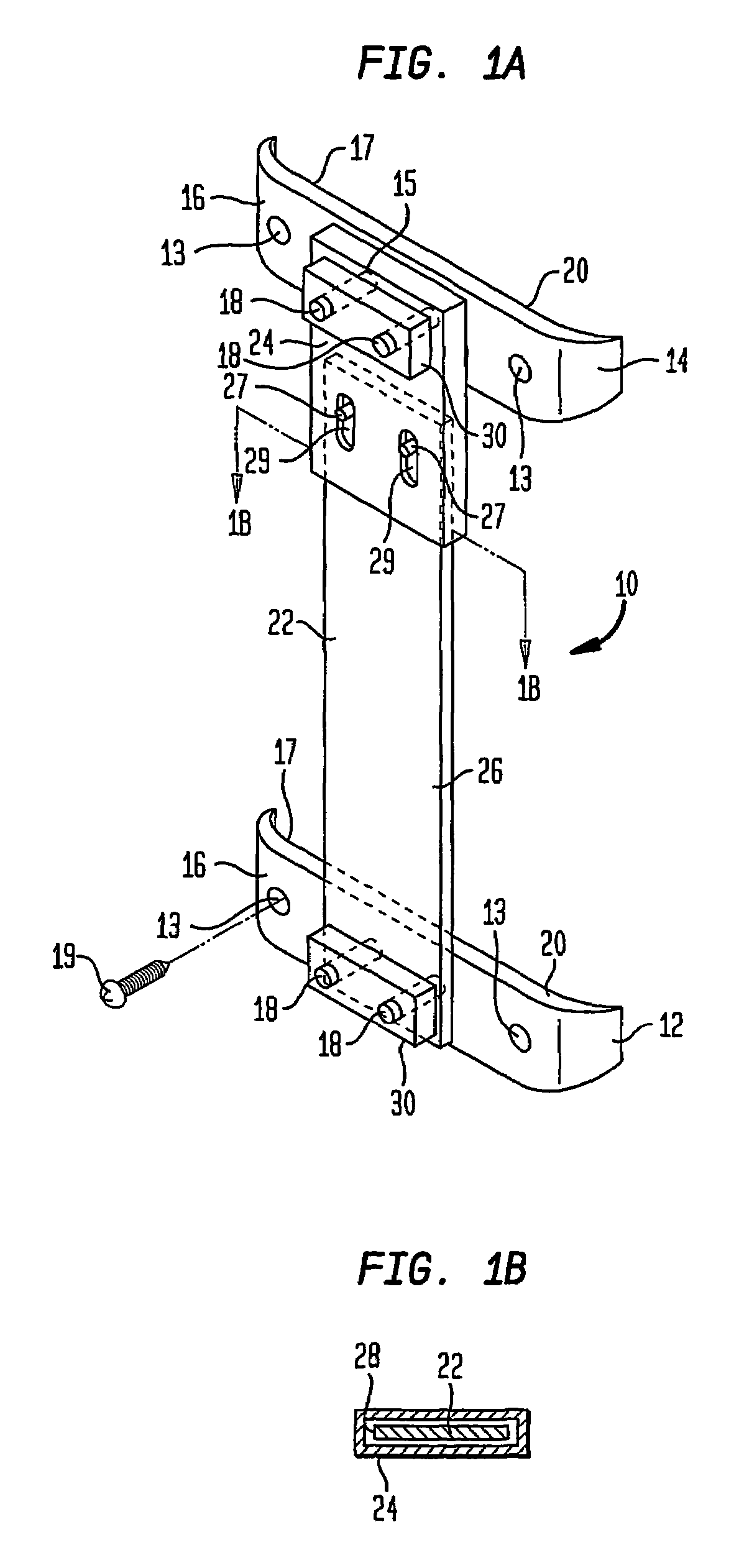
[0040]FIG. 1a is an isometric representation of the mobile sleeve 10 that is provided with a series of components that when assembled together cause mobile sleeve 10 to have a shape generally in the form of an uppercase letter “I.” A lowermost template 12 and an uppermost template 14 each have an anterior side 16, a posterior side 17 (not shown in this figure), and an outer edge 20 that extends around the perimeter between posterior side 17 and anterior side 16. A respective pair of posts 18 extend orthogonally outward from each of the anterior sides of the lowermost and uppermost templates. Two posts 18 are located on each anterior side 16 of lowermost template 12 and uppermost template 14. Posts 18 are used to connect lowermost template 12 and uppermost template together and, as will be described hereinafter, to facilitate incorporation of additional levels to the overall structure whereby more than two vertebra are to be fused. Lowermost template 12 and uppermost template 14 each...


PUM


Abstract

An arrangement and method of use for supporting a plurality of vertebrae in a cervical column in predetermined spatial relation and for facilitating a spinal fusion procedure. A plurality of templates (12, 14) couple to respectively associated vertebrae at anterior lateral surfaces thereof. Such coupling is effected with fasterners, such as bone screws (19). The templates are slidingly coupled to each other by a coupler assembly (22) whereby they are displaceable along a path over a limited distance that is substantially parallel to the longitudinal axis of the cervical column. The sliding displacement between the templates is limited by a pair of protruding tongues (27) that extend through elongated apertures (29). The elongated dimension of the apertures determines the extent of sliding travel, which extent is established to accommodate subsidence of the bone fusion and to prevent separation of the sliding elements of the coupler assembly. The coupler assembly is coupled to each template by engagement between posts (18) and post holes (15). Additionally, locking plates and fasteners, such as threaded fasteners, are used to ensure the security of the engagement between the templates and the coupler assembly. Sequential replication of the arrangement enables three or more vertebrae to be supported in the determined spatial relation.

Description

RELATIONSHIP TO OTHER PATENT APPLICATION[0001]This application is a 371 of PCT / US02 / 12772 filed Apr. 4, 2002 and claims the benefit of U.S. Provisional Patent Application No. 60 / 281,579, filed Apr. 4, 2001.BACKGROUND OF THE INVENTION[0002]1. Field of the Invention[0003]This invention relates generally to spinal implant systems, and more particularly, to a mobile sleeve structure that maintains a determinable spatial relationship between adjacent vertebrae.[0004]2. Description of the Related Art[0005]There is a need in the field of neurosurgery for spinal implant systems that enable surgeons to maintain a determinable spatial relationship between adjacent vertebrae during vertebral fusion procedures. A typical vertebral fusion procedure involves implanting a bone graft or cage element into the intervertebral region known that normally would be occupied by a disc. Patients that suffer from degenerative disc disorders may be required to undergo a surgical procedure that involves the fu...

Claims


Application Information

Patent Timeline
Patent Type & Authority Patents(United States)
IPC IPC(8): A61B17/80A61B17/70A61F2/00A61F2/02A61F2/28A61F2/30A61F2/44
CPCA61B17/70A61F2/4455A61B17/8023A61F2/30744A61F2002/2835A61F2002/30517A61F2002/30538A61F2002/30556A61F2002/30604A61F2002/30616A61F2002/30774A61F2002/30779A61F2002/30785A61F2002/30787A61F2002/30975A61F2002/4475A61F2220/0025A61F2250/0006A61F2250/0009A61F2002/30593
Inventor RAPP, LAWRENCE G.
Owner RAPP LAWRENCE G
Why Eureka
Try Eureka