Controller for motor

a controller and motor technology, applied in the direction of motor/generator/converter stopper, dynamo-electric gear control, motor/generator/converter stopper, etc., can solve the problem of inability to change the field control amount between the driving mode and the power generating mode, inconveniently preventing flexible changes of the controllable output torque range, etc. problem, to achieve the effect of reducing the shortage of field weakening, reducing the shortage of field weak

Inactive Publication Date: 2009-06-16
HONDA MOTOR CO LTD
View PDF9 Cites 15 Cited by
  • Summary
  • Abstract
  • Description
  • Claims
  • Application Information

AI Technical Summary

Benefits of technology

[0010]The present invention has been made with a view of the aforesaid background, and it is an object of the invention to provide a controller for a motor that is capable of reducing the amount of energization required to actuate, under a predetermined condition, a motor having two rotors that are concentrically disposed.
[0011]To this end, according to the present invention, there is provided a controller for a motor adapted to control an operation of a permanent magnet field type rotary motor having a first rotor and a second rotor, which have a plurality of fields made of permanent magnets and which are disposed around a rotating shaft, by field control carried out by changing a rotor phase difference as the phase difference between the first rotor and the second rotor. The field control includes field weakening control for reducing the magnetic fluxes of the fields of the motor and field strengthening control for increasing the magnetic fluxes of the fields of the motor.

Problems solved by technology

Hence, the conventional control for weakening the field, which depends merely on the number of revolutions, tends to inconveniently result in an excessive or insufficient control amount for weakening the field.
This inconveniently prevents flexible changes of the controllable range of output torque or the number of revolutions of the motor.
Furthermore, when changing the phase difference between the first rotor and the second rotor by the number of revolutions or a centrifugal force, it is disadvantageous that the field control amount cannot be changed between the driving mode and the power generating mode.

Method used


Image

  • Controller for motor
  • Controller for motor
  • Controller for motor

Examples


Embodiment Construction

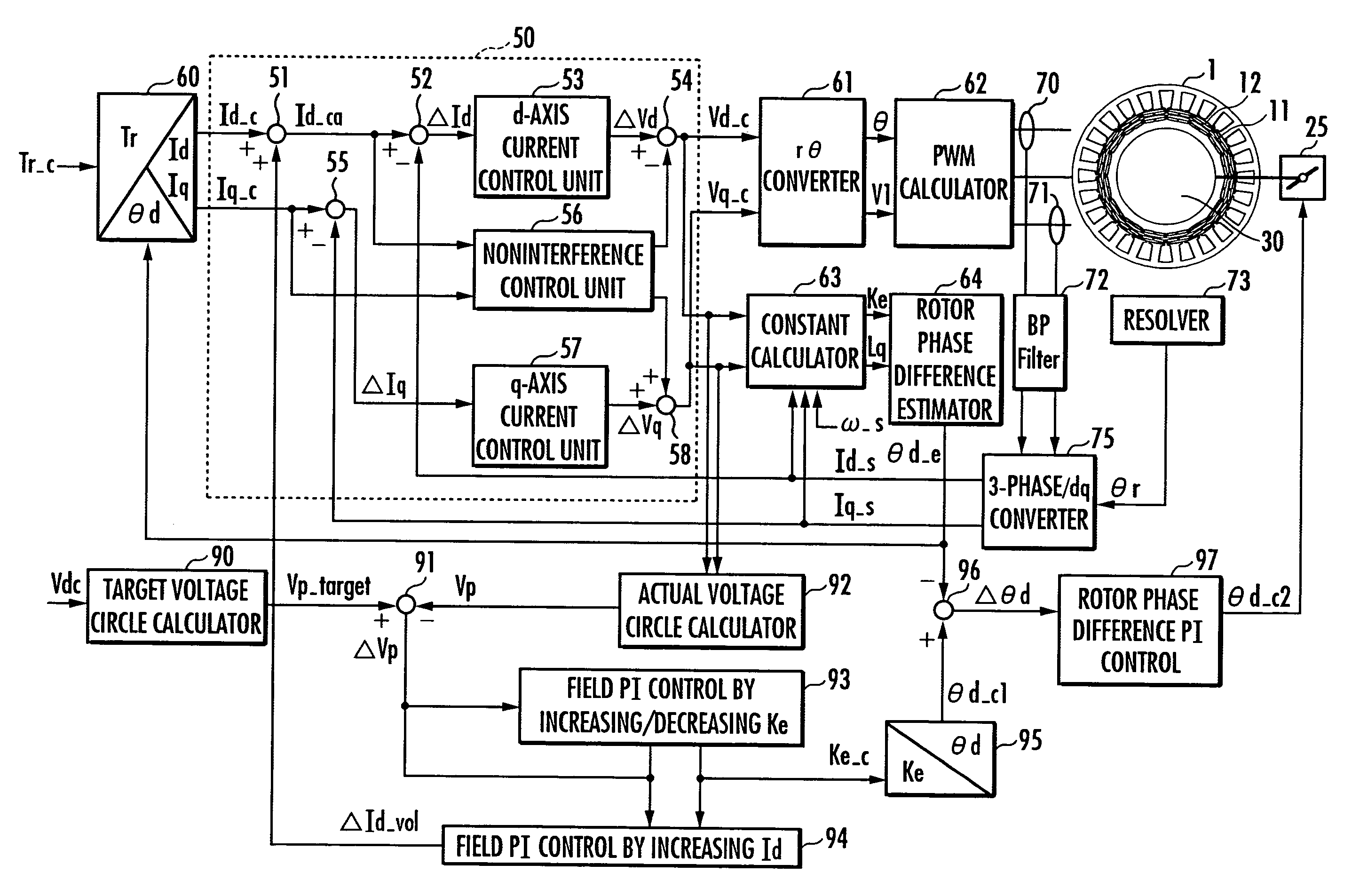
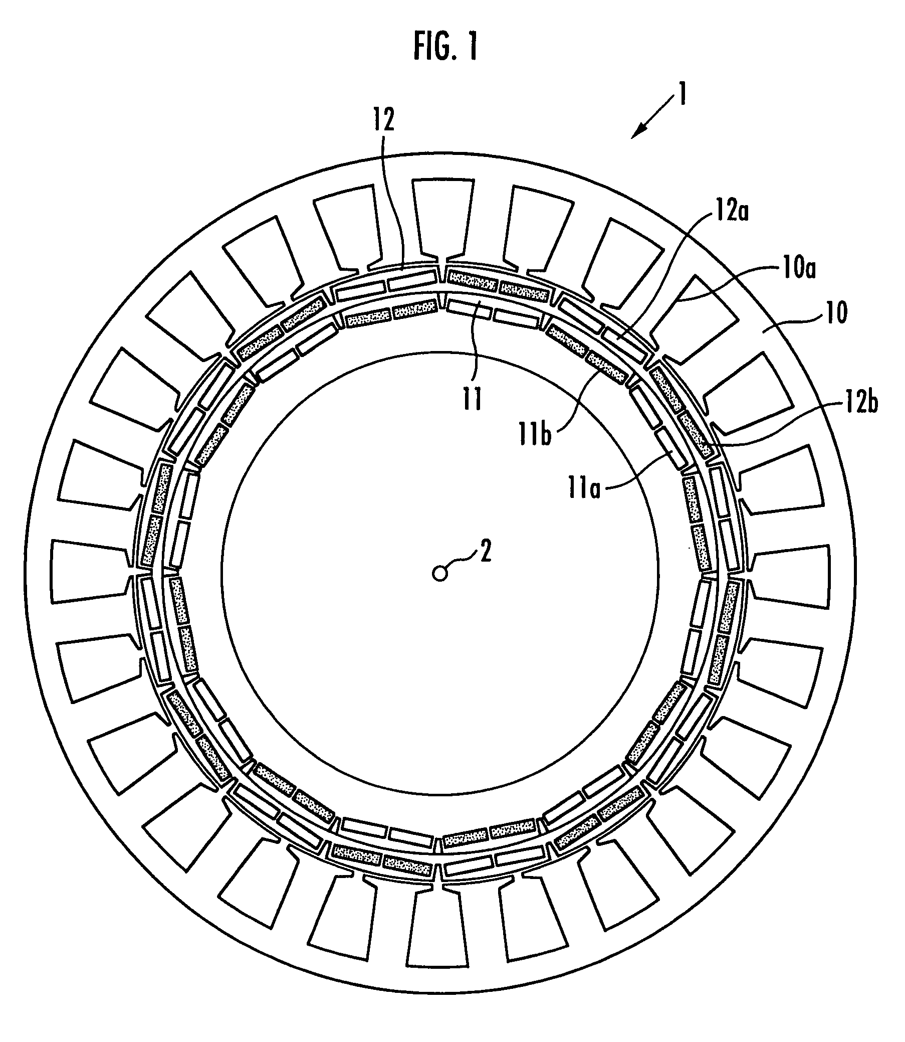
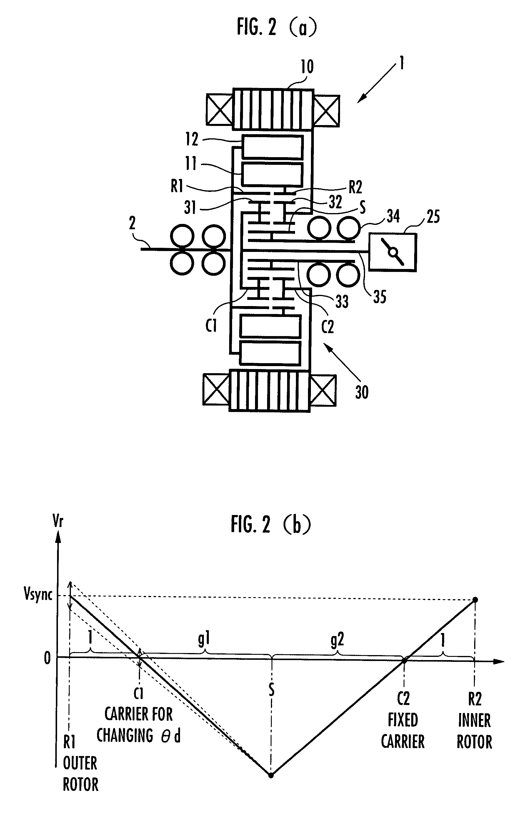
[0036]An embodiment of the present invention will be explained with reference to FIG. 1 to FIG. 11. FIG. 1 is a configuration diagram of a DC brushless motor provided with a double rotor, FIGS. 2(a) and 2(b) are a configuration diagram and an operation explanatory diagram, respectively, of a mechanism for changing a phase difference between an outer rotor and an inner rotor of the DC brushless motor shown in FIG. 1, FIG. 3 and FIG. 4 are explanatory diagrams of advantages provided by changing the phase difference between the outer rotor and the inner rotor, FIG. 5 is a control block diagram of a controller for a motor, FIG. 6 is a voltage vector diagram in a d-q coordinate system, FIG. 7 shows explanatory diagrams of a map for determining a rotor phase difference from an induced voltage constant and a map for determining a rotor phase difference from an induced voltage constant and an inductance of a q-axis armature, FIG. 8 shows explanatory diagrams of advantages of field weakening...


PUM


Abstract

A controller for a motor is capable of reducing the amount of energization required to operate a motor under a predetermined condition, the motor having two rotors disposed around a rotating shaft. The controller includes an induced voltage constant command value determiner which determines an induced voltage constant command value (Ke_c) of a motor such that a difference (ΔVp) between a target voltage circle radius (Vp_target) and a magnitude (Vp) of the vector sum of a d-axis voltage command value and a q-axis voltage command value of the motor decreases, a rotor phase difference acquirer and a rotor phase difference command value determiner which change a rotor phase difference on the basis of the Ke_c, and a field weakening current correction value calculator which determines a field weakening correction current ΔId_vol on the basis of ΔVp and adds the determined ΔId_vol to the d-axis current command value in the case where Vp cannot be reduced to Vp_target or less by reducing Ke_c to a lower limit of a rotor phase difference changing range.

Description

BACKGROUND OF THE INVENTION[0001]1. Field of the Invention[0002]The present invention relates to a controller for a motor adapted to carry out field weakening control of a permanent magnet field type rotary motor by changing a phase difference between two rotors disposed around a rotating shaft.[0003]2. Description of the Related Art[0004]Hitherto, there has been known a permanent magnet field type rotary motor which is equipped with a first rotor and a second rotor concentrically provided around a rotating shaft thereof and which is adapted to conduct field weakening control by changing a phase difference between the first rotor and the second rotor according to a rotational velocity (refer to, for example, Japanese Patent Laid-Open Publication No. 2002-204541).[0005]In such a conventional motor, the first rotor and the second rotor are connected through the intermediary of a member that is displaced in the radial direction when subjected to a centrifugal force. The motor is config...

Claims


Application Information

Patent Timeline
Patent Type & Authority Patents(United States)
IPC IPC(8): H02P21/00H02K16/02H02P6/06H02P6/08H02P6/28H02P21/06H02P21/22H02P27/04H02P27/08
CPCH02P21/0089H02P21/02H02P2207/03
Inventor ATARASHI, HIROFUMIISEGAWA, HIROYUKI
Owner HONDA MOTOR CO LTD
Why Eureka
Try Eureka