Agile illumination for biometric authentication
- Summary
- Abstract
- Description
- Claims
- Application Information
AI Technical Summary
Benefits of technology
Problems solved by technology
Method used
Image


Examples
Embodiment Construction
[0019]The particular values and configurations discussed in these non-limiting examples can be varied and are cited merely to illustrate at least one embodiment and are not intended to limit the scope thereof.
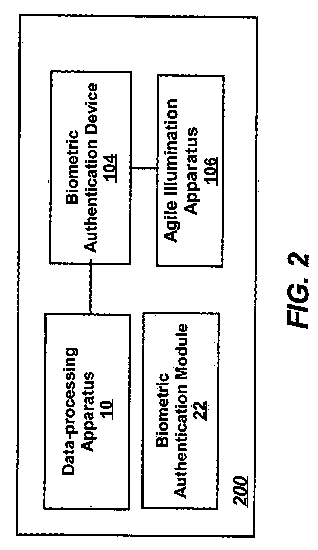
[0020]FIG. 1 illustrates a block diagram of a biometric authentication system 100, which can be implemented in accordance with an alternative embodiment. Note that in FIGS. 1-4, identical or similar parts or elements are generally indicated by identical reference numerals. System 100 includes the use of a computer 10, which can communicate with a biometric authentication device 104, which in turn communicates electrically with an agile illumination apparatus 106 that will be described in greater detail herein. Note that as utilized herein the term “computer” refers generally to any machine for manipulating data according to a list of instructions. Computer 10 can be implemented as, for example, personal computers and their portable equivalent, the laptop computer.
[0021]Computer...
PUM
 Abstract
Description
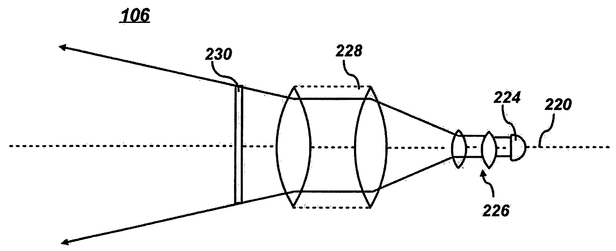
Claims
Application Information
 - Generate Ideas
- Intellectual Property
- Life Sciences
- Materials
- Tech Scout
- Unparalleled Data Quality
- Higher Quality Content
- 60% Fewer Hallucinations
Browse by: Latest US Patents, China's latest patents, Technical Efficacy Thesaurus, Application Domain, Technology Topic, Popular Technical Reports.
© 2025 PatSnap. All rights reserved.Legal|Privacy policy|Modern Slavery Act Transparency Statement|Sitemap|About US| Contact US: help@patsnap.com