Method and apparatus for tissue treatment with laser and electromagnetic radiation

Inactive Publication Date: 2009-06-23
PRO SURG
View PDF56 Cites 51 Cited by
  • Summary
  • Abstract
  • Description
  • Claims
  • Application Information

AI Technical Summary

Benefits of technology

[0020]An advantage of the present invention is that it allows the controlled delivery of laser and electromagnetic radiation energy to target tissue in a localized manner without affecting the surrounding healthy tissue.
[0021]A further advantage of the present invention is that it provides a selective treatment of diseased tissue such as malignant cancer cells, avoiding the need to expose a large portion of a patient's body to toxic radiation.
[0022]A still further advantage of the present invention is that application of laser energy and/or other energy t

Problems solved by technology

The result is uncontrolled tissue destruction, inc

Method used


Image

  • Method and apparatus for tissue treatment with laser and electromagnetic radiation
  • Method and apparatus for tissue treatment with laser and electromagnetic radiation
  • Method and apparatus for tissue treatment with laser and electromagnetic radiation

Examples


Embodiment Construction

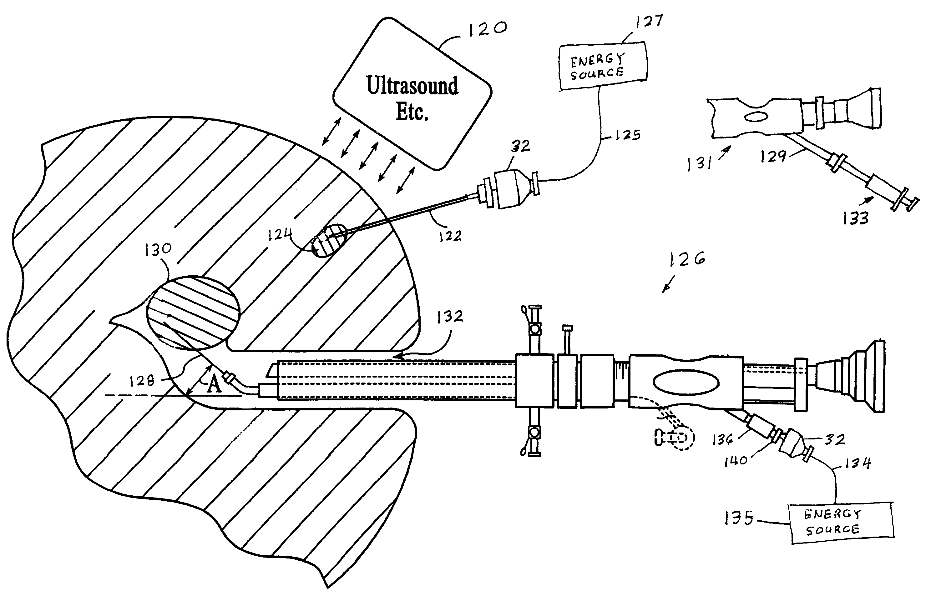
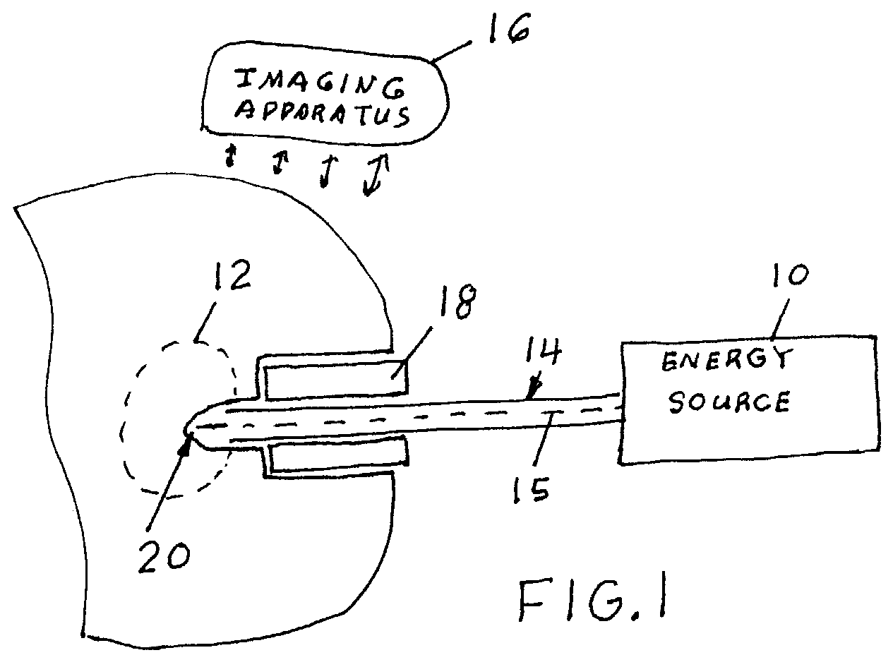
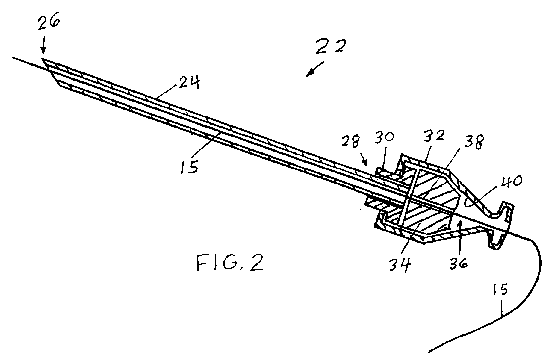
[0053]The present invention is illustrated in the symbolic diagram of FIG. 1 wherein an energy source 10 supplies any of a variety of energy types including laser energy and / or other electromagnetic energy that is transmitted to a target tissue 12 through a transmission device 15. The transmission device is preferably constructed as a device that serves to carry energy from the source to the target tissue without radiating energy along the path. Examples of these types of transmission devices will be given in reference to FIGS. 3A-3C of the drawing. Item 14 in FIG. 1 represents a delivery apparatus that includes the transmission device symbolized by dashed line 15. In one embodiment (FIG. 3C), the delivery apparatus is physically the same as the transmission device. In other embodiments, for example see FIGS. 3B and 3C, the delivery apparatus includes a hollow core needle with a transmission device enclosed within the needle, all for the purpose of delivering the energy. In alternat...


PUM

PropertyMeasurementUnit
Wavelengthaaaaaaaaaa
Energyaaaaaaaaaa

Abstract

A method and apparatus wherein an application of energy is limited to a specific diseased portion of body tissue (target tissue) for the purpose of localizing the treatment to the target tissue and avoiding an adverse effect on surrounding tissue. In one embodiment, access to the target tissue is provided by inserting an energy transmission device through a needle for delivery of the energy into the target tissue. Guidance of the needle is alternatively enhanced through use of an image guidance device. Alternatively, in addition the localized treatment is further controlled by use of an energy-concentrating/enhancement agent and/or photosensitizing/photoselective agent, chromophore dye and viscous substance to cause selective interaction with a specific wavelength of an energy source. The treatment can be further controlled and localized by improving the accuracy and positioning of the delivery device into the target tissue using imaging guidance.

Description

RELATED CASES[0001]This application is a continuation in part of each of U.S. patent application Ser. Nos. 10 / 274,436 and 10 / 274,497, now abandoned both filed Oct. 17, 2002 and both of which are continuations-in-part of U.S. patent application Ser. No. 10 / 193,721 filed on Jul. 10, 2002 (which claims priority from U.S. Provisional Application 60 / 383,015 filed May 23, 2002). which is a continuation-in-part of U.S. patent application Ser. No. 09 / 715,853 filed Nov. 17, 2000, which is a continuation-in-part of U.S. patent application U.S. patent application Ser. No. 09 / 510,537 filed Feb. 22, 2000 (now U.S. Pat. No. 6,461,296), which is a continuation-in-part of U.S. patent application Ser. No. 09 / 105,896 filed Jun. 26, 1998 (U.S. Pat. No. 6,231,591), which is a continuation-in-part of U.S. patent application Ser. No. 08 / 639,199 filed Apr. 26, 1996 (U.S. Pat. No. 5,861,002) The contents of each of these applications is incorporated in this application by reference.BACKGROUND OF THE INVENT...

Claims


Application Information

Patent Timeline
IPC IPC(8): A61B19/00A61F7/00A61B1/018A61B6/12A61B17/00A61B17/22A61B17/34A61B18/00A61B18/14A61K9/00A61K31/03A61K31/335A61K31/337A61K31/355A61M1/00A61N5/06
CPCA61B8/0841A61B17/00234A61B17/3403A61B17/3478A61B18/1477A61B18/149A61K9/0031A61K9/0034A61K31/03A61K31/335A61K31/337A61K31/355A61M1/0064A61B1/018A61B6/12A61B17/3498A61B18/14A61B18/1402A61B18/1442A61B18/1482A61B19/201A61B2017/00026A61B2017/00057A61B2017/00106A61B2017/00274A61B2017/00464A61B2017/22072A61B2017/3411A61B2017/3445A61B2018/00547A61B2018/0091A61B2018/00916A61B2018/00982A61B2018/1253A61B2018/126A61B2018/1425A61B2019/5276A61B2019/5425A61B2218/002A61B2218/007A61M1/0062A61N5/0601A61N5/062A61B90/11A61B2090/378A61B2090/3925A61M1/772
Inventor DESAI, ASHVIN
Owner PRO SURG
Why Eureka
Try Eureka