Container with improved stacking strength and resistance to lateral distortion

a technology of lateral distortion and container, applied in the field of packaging, can solve the problems of not being as strong as the provided resistance, and achieve the effects of improving the top to bottom compression strength, simple, economical and effective way

Inactive Publication Date: 2009-06-23
INT PAPER CO
View PDF16 Cites 4 Cited by
  • Summary
  • Abstract
  • Description
  • Claims
  • Application Information

AI Technical Summary

Benefits of technology

[0009]The tray of the invention has stacking strength superior to a four sided container, and resistance to distortion superior to an eight sided container when transverse forces are applied to the ends of the tray.
[0010]In one embodiment of the invention, for a tray having diagonal corner panels, the diagonal corner panels are oriented from about 35° to about 40°, and in a preferred embodiment 38°, with respect to the longitudinal axis of the tray. The shallower angle of the corner panels, compared with the conventional 45° angle, changes the resultant force vector slightly toward the ends of the tray, increasing resistance to distortion from force applied to the ends of the tray. The shallower angle of the corner panels also results in wider corner panels and concomitant shorter side panels, with comparable or even improved stacking strength over similarly sized eight sided trays with the diagonal corner panels oriented at 45°. These beneficial results are obtained in trays having six, seven or eight sides, for example, with two, three or four diagonal corner panels, respectively.
[0011]In an alternate embodiment, for a tray having diagonal corner panels, at least one corner of the tray is squared. Thus, an eight sided tray, for example, is modified to have one square corner, producing a seven sided tray, or two diagonally opposite corners are made square to produce a six sided tray. The remaining diagonal corner panels may be oriented at any angle, including 38° or 45° relative to the longitudinal axis of the tray, although if oriented at 38° some of the benefits discussed above can be additionally obtained. Although the seven sided tray resists distortion caused by lateral force applied to the side or end of the tray, the resistance is not as great as that provided by the six sided tray. Both the six sided tray and the seven sided tray provide a square corner around which a label can be wrapped so that it is visible from two adjacent sides of the tray. The seven sided tray can be formed from the same blank size as the standard eight sided package, and neither its machine nor manual assembly is any more complicated than the standard eight sided package. Further, the top to bottom compression resistance of the seven sided tray is 10% to 25% greater than a standard four sided tray.
[0012]In the six sided tray, the two diagonal corner panels not squared are lengthened approximately 30% as compared with a conventional eight sided tray of comparable size. The longer diagonal corner panels increase the top to bottom compression strength of the six sided tray so that it is about the same as a similar size eight sided tray. This compression performance of the six sided tray was unexpected. Moreover, better fit of the cover was obtained because of the two diagonally opposed square corners. Further, machine conversion from four sided to six sided is easier than from four sided to eight sided. The six sided tray may be adapted for either machine set up or manual set up.
[0013]The invention is a simple, economical and effective way to maintain stacking strength and improve resistance to distortion from force applied laterally to the sides or ends of trays having diagonal corner panels. Trays incorporating the invention, whether orienting the diagonal corner panels at 38°, or squaring at least one corner, or both, can be produced and generally handled with existing machinery.

Problems solved by technology

Although the seven sided tray resists distortion caused by lateral force applied to the side or end of the tray, the resistance is not as great as that provided by the six sided tray.

Method used


Image

  • Container with improved stacking strength and resistance to lateral distortion
  • Container with improved stacking strength and resistance to lateral distortion
  • Container with improved stacking strength and resistance to lateral distortion

Examples


first embodiment

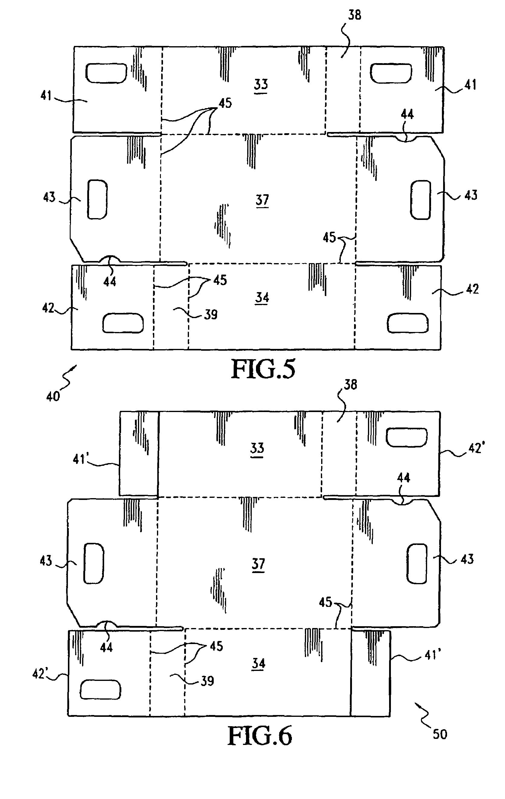
[0043]An alternate form of the six sided tray of the first embodiment is depicted at 50 in FIG. 6. The tray in this form of the invention is also configured for machine set up, but the end panels 41′ and 42′ do not overlap with one another. In other respects, the tray shown in this figure is essentially the same as that illustrated in FIGS. 3 and 5.

[0044]Another alternate form of the first embodiment is indicated generally at 60 in FIGS. 7-9. In this form of the first embodiment, the container or tray is configured for manual set up, and has a bottom wall 61, opposite parallel side walls 62 and 63, opposite parallel end walls 64 and 65, an opposed pair of diagonal corner panels 66 and 67, and two diagonally opposed square corners 68 and 69.

[0045]As seen best in FIG. 8, the container of FIG. 7 is erected from a unitary paperboard blank having overlapped end panels 70, 71 and 72 that form the end walls 64 and 65, and which are held in assembled relationship by a self locking arrangeme...

second embodiment

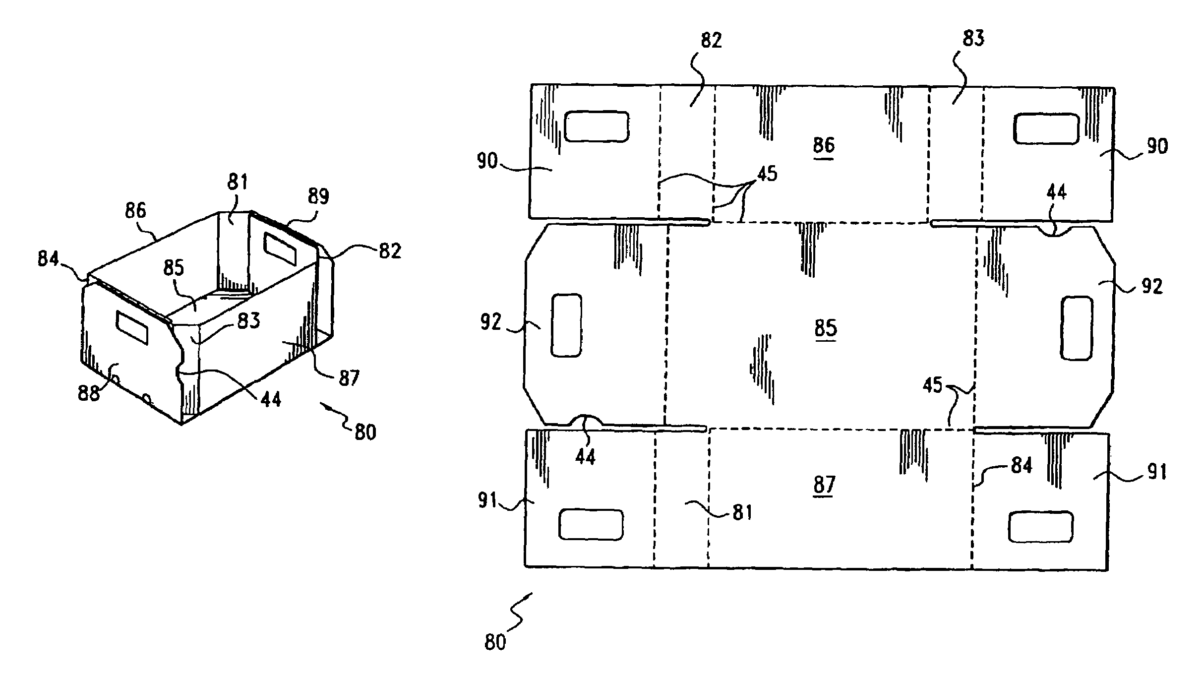
[0048]the invention is indicated at 80 in FIGS. 10-14, wherein the container has seven sides. In a first form of this embodiment, shown in FIGS. 10-12, the container is configured for machine set up, and has three corners 81, 82 and 83 oriented diagonally and only one corner 84 that is squared, producing a seven sided container. In all other respects, this embodiment is essentially the same as that shown in FIGS. 3 and 5. The container 80 has a bottom wall 85, opposed parallel side walls 86 and 87, opposed parallel end walls 88 and 89, diagonal corner panels 81, 82 and 83, and the single square corner 84. As seen best in FIG. 12, which depicts the unitary paperboard blank from which the container 80 is erected, the end walls each comprise end panels 90, 91 and 92, which are overlapped and glued together by machine in setting up the container.

[0049]A first modification of the second embodiment is shown at 100 in FIGS. 13 and 14. In this modification, the container is configured for m...

third embodiment

[0051]the invention is shown in FIGS. 16-21, wherein the container has eight sides, and the four diagonal corner panels are each oriented at an angle of 38° with respect to the longitudinal axis of the container.

[0052]In a first form of this third embodiment, depicted at 110 in FIGS. 17 and 18, the container is configured for manual set up and to that end has notches 111 and 112 in the top edges of end panels 113 and 114 that interlock with a roll over flap 115 on the top edge of end panels 116. Pairs of cuts 117 and 118 are made transversely across the cut line 119 between the roll over flap 115 and its associated end panel 116, and these cuts are spaced apart a distance approximately the same as the width of the notches 111 and 112 in panels 113 and 114. The cuts define short, narrow webs 120 and 121, which connect the roll over flap to its associated end panel, and in a preferred form, the webs are crushed from the inside of the container. Thus, when the roll over flap is folded ...


PUM


Abstract

A container made from corrugated paperboard has more than four sides and is constructed to resist distortion when force is applied to the ends or sides of the container, and also to resist crushing when containers are stacked on top of one another. In one embodiment, the container has six sides, with two side walls, two end walls, and two diagonally opposed diagonal corner panels and two diagonally opposed square corners. In another embodiment, the container has seven sides, with two side walls, two end walls, and three diagonal corner panels and one square corner. In a further embodiment, the container has eight sides, with two side walls, two end walls, and four diagonally opposed diagonal corner panels. In this embodiment, the diagonal corner panels are oriented so that they subtend an angle of from about 35° to about 40°, and preferably 38°, with respect to the longitudinal axis of the container. The diagonal corner panels in the other embodiments may also be oriented at 38°, or from about 35° to about 40°.

Description

[0001]This application claims the benefit of U.S. Provisional Application No. 60 / 307,681, filed Jul. 25, 2001, entitled “Poultry Pack”.BACKGROUND OF THE INVENTION[0002]1. Field of the Invention[0003]This invention relates to packaging. More specifically, the invention relates to a multi-sided container or box made of corrugated paperboard. In particular, the invention relates to a corrugated paperboard tray for containing poultry products, wherein the tray has improved stacking strength and resistance to distortion from lateral forces applied to the sides or ends of the tray.[0004]2. Prior Art[0005]Various styles of paperboard boxes are known in the prior art for containing a variety of products. Conventional boxes may have four sides and be square or rectangular in plan view, or they may have eight sides, with opposed pairs of parallel side and end walls and diagonal corner panels oriented at 45° to the longitudinal axis of the box and connecting adjacent side and end walls.[0006]E...

Claims


Application Information

Patent Timeline
Patent Type & Authority Patents(United States)
IPC IPC(8): B65D5/20B65D21/032B65D5/00B65D5/22B65D5/28B65D5/42B65D5/44B65D5/468B65D5/60
CPCB65D5/002B65D5/22B65D5/28B65D5/4279B65D5/443B65D5/4608B65D5/60Y10S229/918
Inventor QUAINTANCE, BENJAMIN W.
Owner INT PAPER CO
Why Eureka
Try Eureka