Magic mirror and method for manufacturing a magic mirror
a technology of magic mirrors and mirrors, applied in the field of magic mirrors, can solve the problems of high cost, high cost, and high cost of conventional casting and polishing steps, and achieve the effect of low cost and simple and quick methods
- Summary
- Abstract
- Description
- Claims
- Application Information
AI Technical Summary
Benefits of technology
Problems solved by technology
Method used
Image
Examples
second embodiment
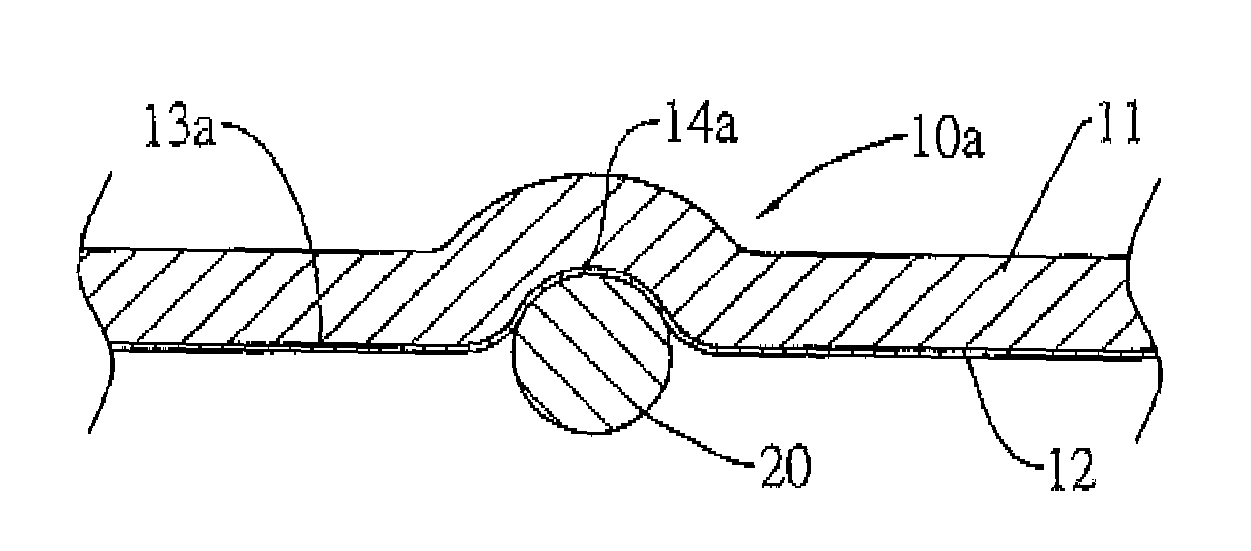
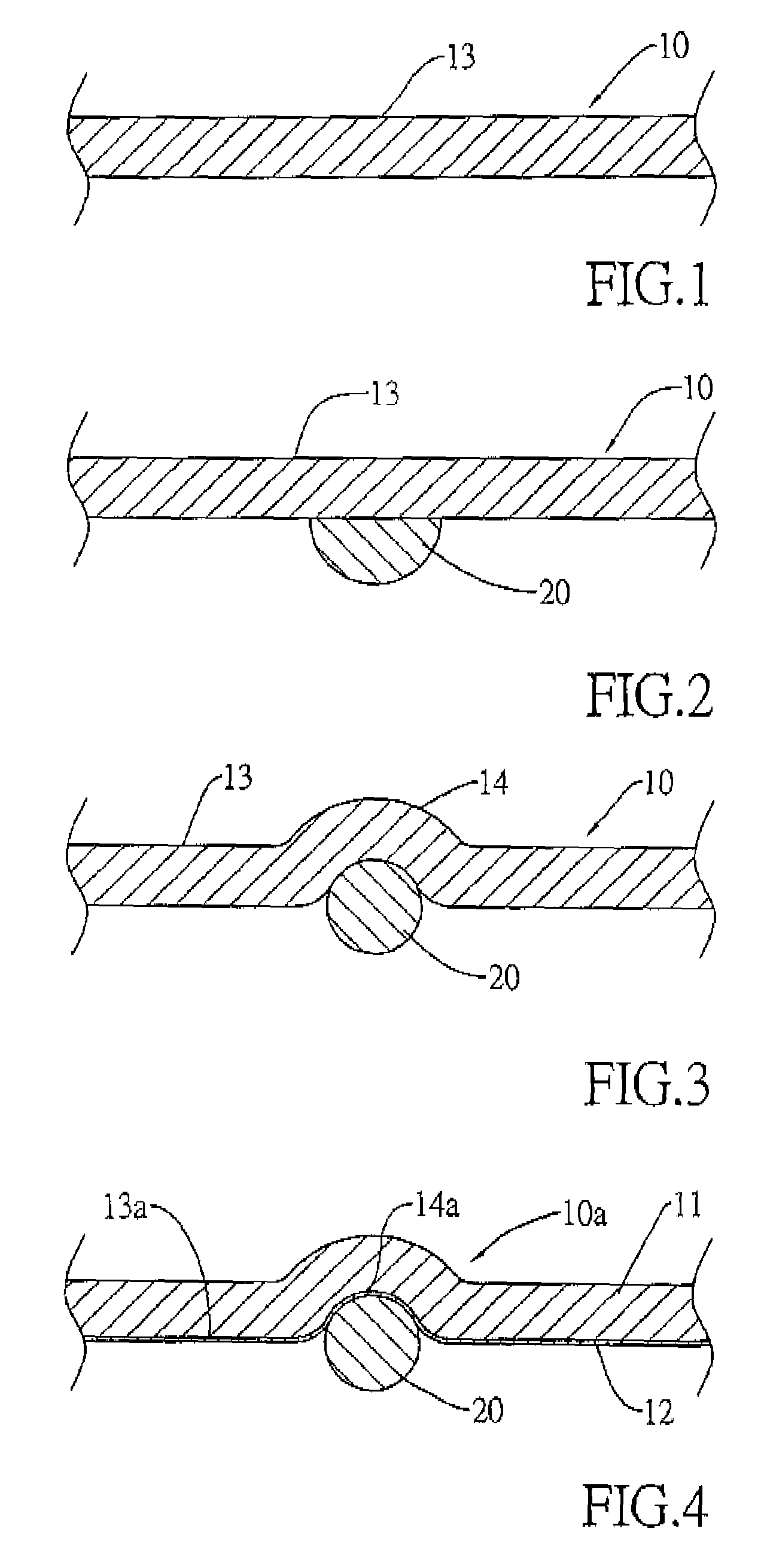
[0022]With reference to FIG. 2, the patterning preparing step is drawing a pattern outline on the rear surface of the mirror substrate (10, 10a) opposite to the reflective surface (13, 13a) by attaching an adhesive (20) to the rear surface. In the method, the adhesive (20) is attached to the outside surface of the reflective layer (12). The adhesive (20) has a volume and a contract rate of volume being positive or negative and is capable of changing the volume after solidifying. When the contract rate of volume is positive, the adhesive (20) contracts and becomes smaller after solidifying. When the contract rate of volume is negative, the adhesive (20) expands and becomes larger after solidifying. The adhesive (20) may be an ultraviolet (UV) adhesive capable of solidifying after receiving UV light, a thermal adhesive capable of solidifying after heated or a mixture of the UV and thermal adhesive.
[0023]With reference to FIGS. 3 and 4, the solidifying step is solidifying the adhesive ...
third embodiment
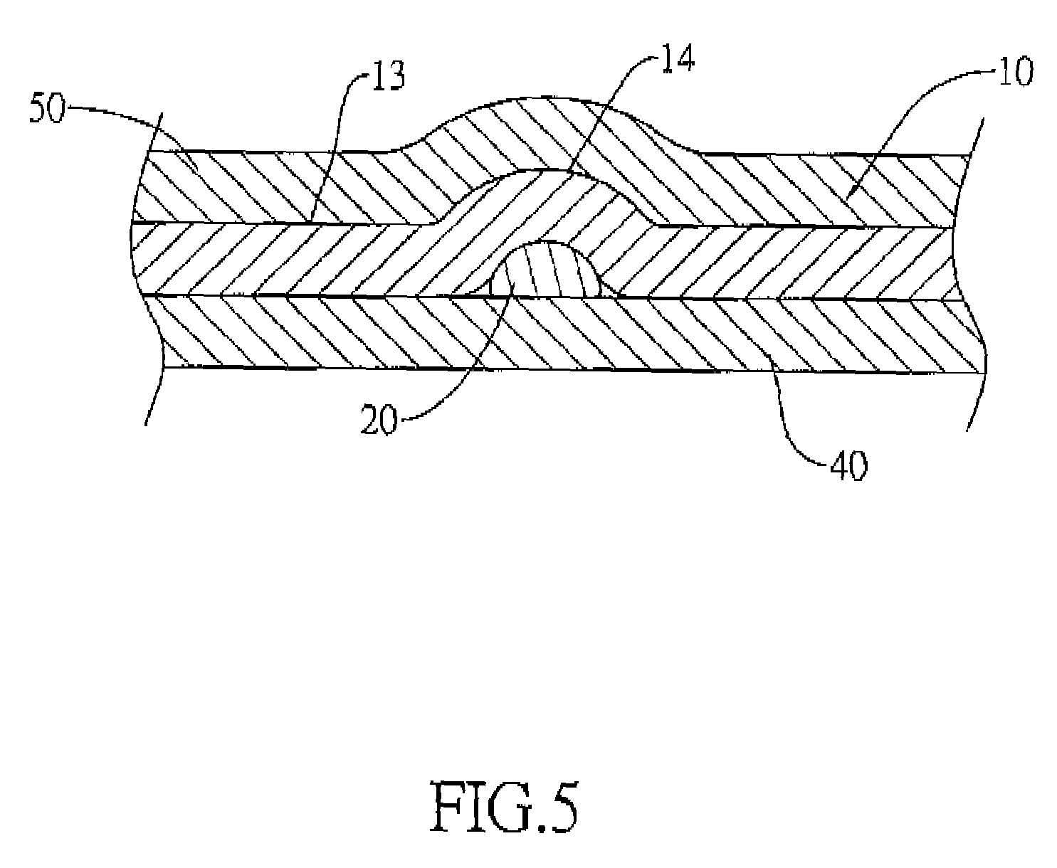
[0024]With reference to FIG. 5, the method further comprises a reinforcing step after the solidifying step. The reinforcing step is mounting a reinforcing backplate (40) on the rear surface of the mirror substrate (10, 10a) and mounting a transparent reinforcing front plate (50) on the front surface of the mirror substrate (10, 10a). The backplate (40) and the transparent front plate (50) strengthen the magic mirror and prevent the pattern from being damaged.
[0025]With reference to FIGS. 7 and 8 aligned with each other, when the parts of the reflective surface (13, 13a) corresponding to the curvature variations (14, 14a) are convex, corresponding parts of the projected image (30) has a low brightness as compared with non-corresponding parts of the projected image (30). When the parts of the reflective surface (13, 13a) corresponding to the curvature variations (14, 14a) are concave, the corresponding parts of the projected image (30) has a high brightness as compared with non-corres...
PUM
| Property | Measurement | Unit |
|---|---|---|
| thickness | aaaaa | aaaaa |
| volume | aaaaa | aaaaa |
| transparent | aaaaa | aaaaa |
Abstract
Description
Claims
Application Information
 - R&D
- Intellectual Property
- Life Sciences
- Materials
- Tech Scout
- Unparalleled Data Quality
- Higher Quality Content
- 60% Fewer Hallucinations
Browse by: Latest US Patents, China's latest patents, Technical Efficacy Thesaurus, Application Domain, Technology Topic, Popular Technical Reports.
© 2025 PatSnap. All rights reserved.Legal|Privacy policy|Modern Slavery Act Transparency Statement|Sitemap|About US| Contact US: help@patsnap.com


