System and method for identifying automation components

a technology of automation components and identification systems, applied in the field of system for identifying automation components, can solve the problems of production losses, adverse effects on the quality of production processes, and considerable effort required in such instances to loca

Active Publication Date: 2009-06-23
SIEMENS AG
View PDF19 Cites 8 Cited by
  • Summary
  • Abstract
  • Description
  • Claims
  • Application Information

AI Technical Summary

Benefits of technology

[0005]An object of the invention is to specify a system for identifying automation components, which allows the identity of the respectively connected components to be determined in a simple and economical manner. The system should also be suitable for adding in stages later.
[0007]The invention is based on the knowledge that when installing new equipment and also when maintaining existing equipment there is a latent risk that the wrong components will be connected and not identified. This can have a significantly adverse effect on the quality of the production process and the products themselves and can ultimately lead to production losses. Considerable effort is required in such instances to locate and eliminate the cause of the problem. With the claimed system however every automation component to be identified is provided with an identification unit. The task of the identification unit is to output an identification code on activation, said identification code allowing unique identification of the associated component. The identification unit can thereby be mounted on a component later or can be connected inseparably to a component or integrated in a component during production of said component. The identification code is read with the aid of the read unit, which is for example disposed in or connected to the peripheral modules of the automation system or an operating unit of the automation system. This allows the automation system to identify the respectively connected components independently and thereby verify and monitor the correctness of the equipment.
[0008]The identification unit and the read unit can communicate in a simple manner using existing transmission paths in that the read unit is provided for connection to a peripheral module and / or an operating device of the automation system.
[0010]Independent operating safety of the identification units can be achieved in that the read unit is provided to inject the energy required to supply the identifications units into the peripheral channel.

Problems solved by technology

This can have a significantly adverse effect on the quality of the production process and the products themselves and can ultimately lead to production losses.
Considerable effort is required in such instances to locate and eliminate the cause of the problem.

Method used


Image

  • System and method for identifying automation components
  • System and method for identifying automation components
  • System and method for identifying automation components

Examples


Embodiment Construction

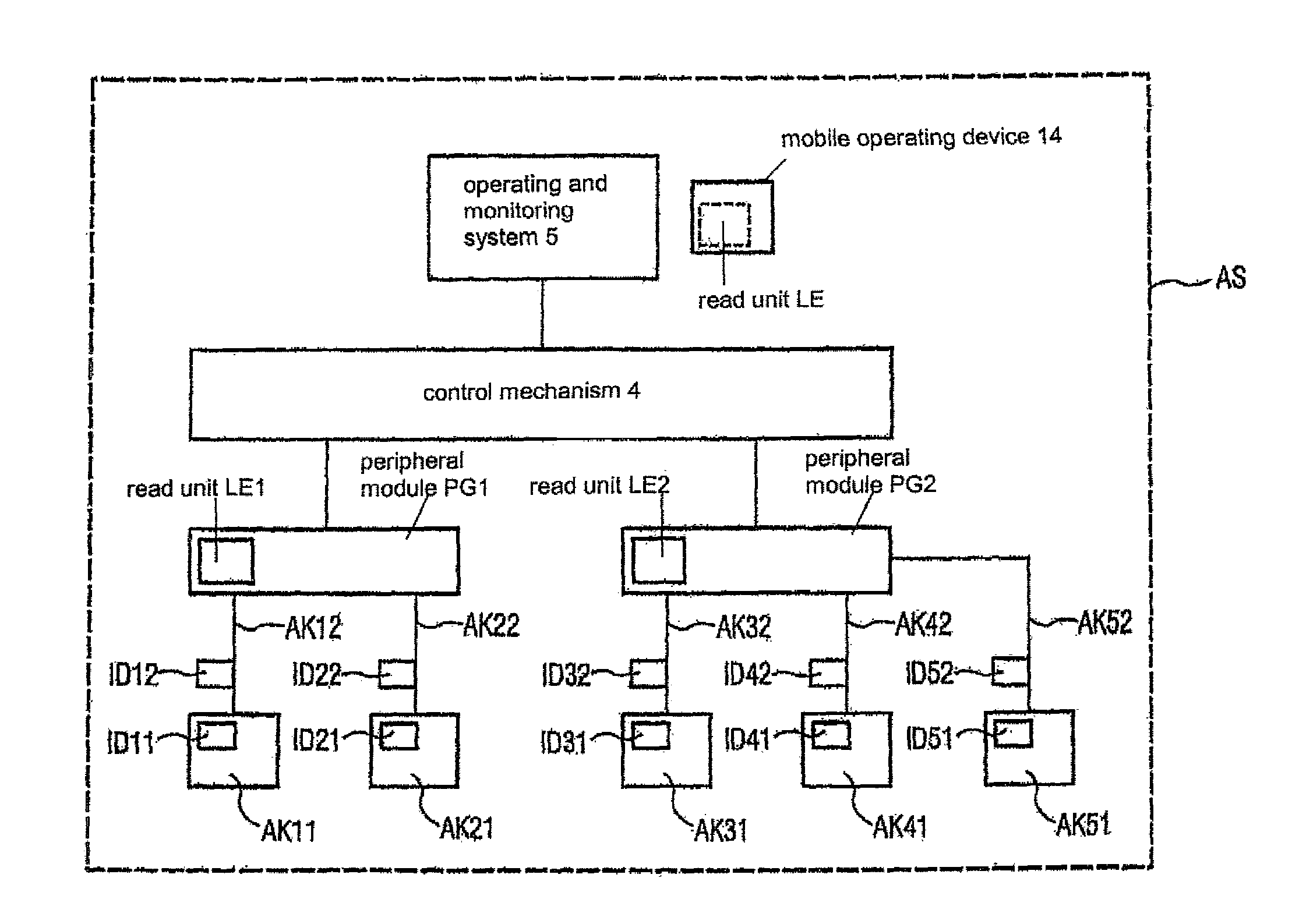
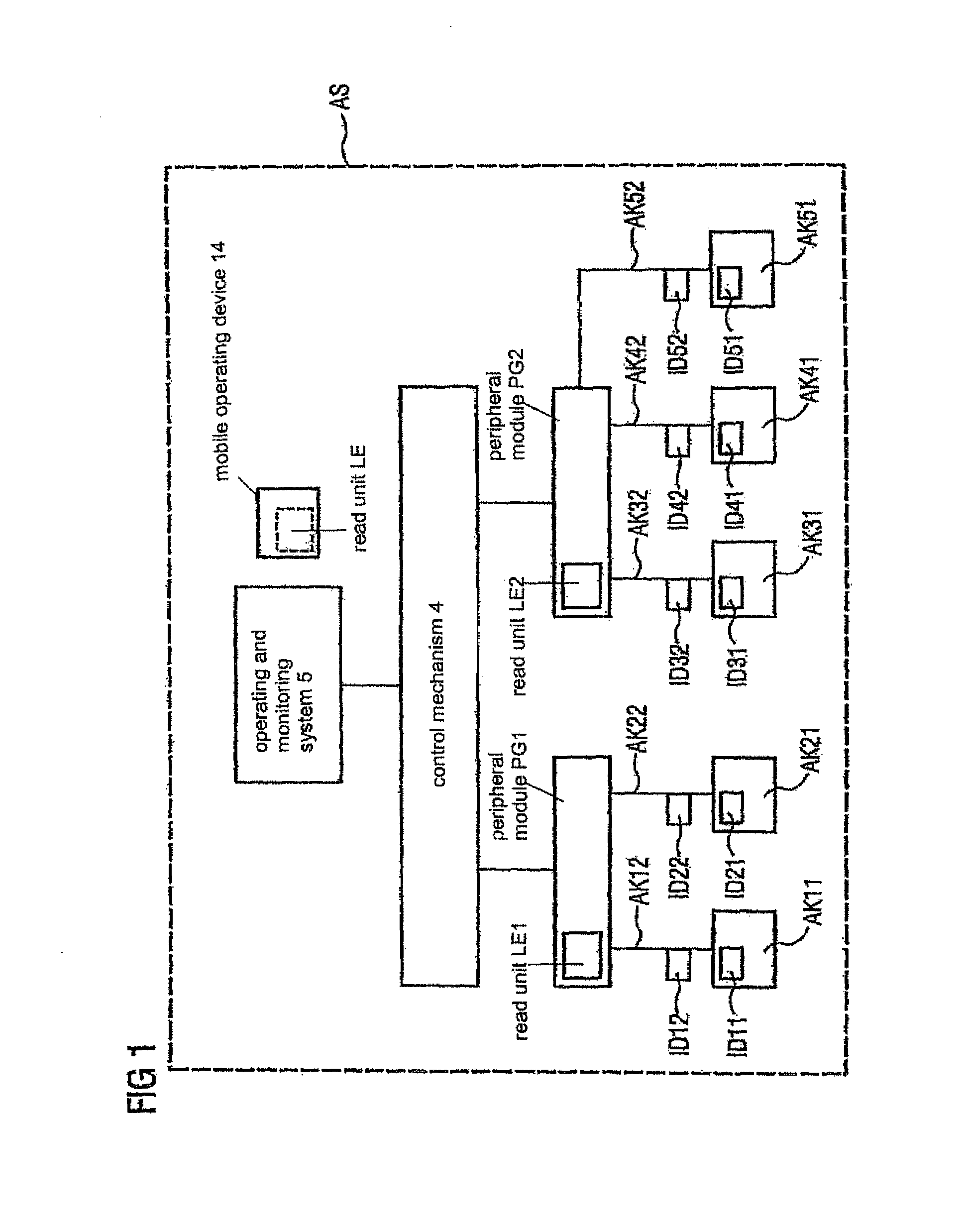
[0020]FIG. 1 shows the basic principles of an automation system AS. The automation system AS comprises automation components AK11 . . . AK52, for example sensors, actuators and other line components. The automation components AK11 . . . AK52 are connected respectively to peripheral devices PG1, PG2, while the peripheral devices PG1, PG2 are in turn connected to a control mechanism 4. An operating and monitoring system 5, which is connected to the controller 4, serves as the user interface. Identification units ID11 . . . ID52 are assigned respectively to the automation components AK11 . . . AK52. The term “automation component” here is so comprehensive that it includes sensors and actuators as well as connection and line components, including cables, etc. The identification units ID11 . . . ID52 each have a storage unit, in which an identification code uniquely identifying the automation components AK11 . . . AK52 is stored. Each automation component AK11 . . . AK52 is thereby chara...


PUM


Abstract

The invention relates to a system and a method for identifying automation components, particularly sensors, actuators and wiring components. According to the invention, each component (sensor, actuator, cable, compensation box, etc.) that is to be identified is equipped with an identification unit in which a code for identifying the automation component is stored and which outputs said identification code when being activated. Preferably, the identification unit comprises an electronic circuit (e.g. an RFID chip or a discreet circuit) while being provided with galvanically insulating (inductive, capacitive, radio-based) or galvanically conducting coupling to the component that is to be identified. The identification unit can be subsequently mounted on a component or can be inseparably connected thereto already during the production of the component.

Description

CROSS REFERENCE TO RELATED APPLICATIONS[0001]This application is a continuation-in-part application of the International Application No. PCT / EP2004 / 007587, filed Jul. 9, 2004 and claims the benefit there of. This application further claims the benefit of German Application No. 10335035.7, filed Aug. 1, 2003 the priority of which has been claimed by the above-mentioned International Application No. No. PCT / EP2004 / 007587. Each of the above-referenced applications are incorporated by reference herein by their entirety.FIELD OF INVENTION[0002]The invention relates to a system for identifying automation components, in particular sensors, actuators and line components of an automation system. The invention also relates to a method for identifying automation components, an identification unit and a read unit for a system for identifying automation components.BACKGROUND OF INVENTION[0003]The invention is deployed in particular in the field of automation technology. Automated production and ...

Claims


Application Information

Patent Timeline
Patent Type & Authority Patents(United States)
IPC IPC(8): G08B13/14G05B19/12G05B19/418
CPCG05B19/12G05B19/4183G05B2219/25297G05B2219/31034G05B2219/31283G05B2219/33203Y02P90/02
Inventor GUNTHER, HARALDMUNZ, DIETER
Owner SIEMENS AG
Why Eureka
Try Eureka